


Troubleshooting (OP: Unified ON/OFF Controller)
Si39-504
250
Troubleshooting
6.3
Display “Under Centralized Control” Blinks (Repeats
Double Blink)
Remote
Controller
Display
“under centralized control” (Repeats double blink)
Applicable
Models
Unified ON/OFF controller
Method of
Malfunction
Detection
Detect the malfunction according to DIII-NET transmission data.
Malfunction
Decision
Conditions
When no central control addresses are set to indoor units.
When no indoor units are connected within the control range.
Supposed
Causes
Central control address (group No.) is not set for indoor unit.
Improper control range setting switch
Improper wiring of transmission wiring
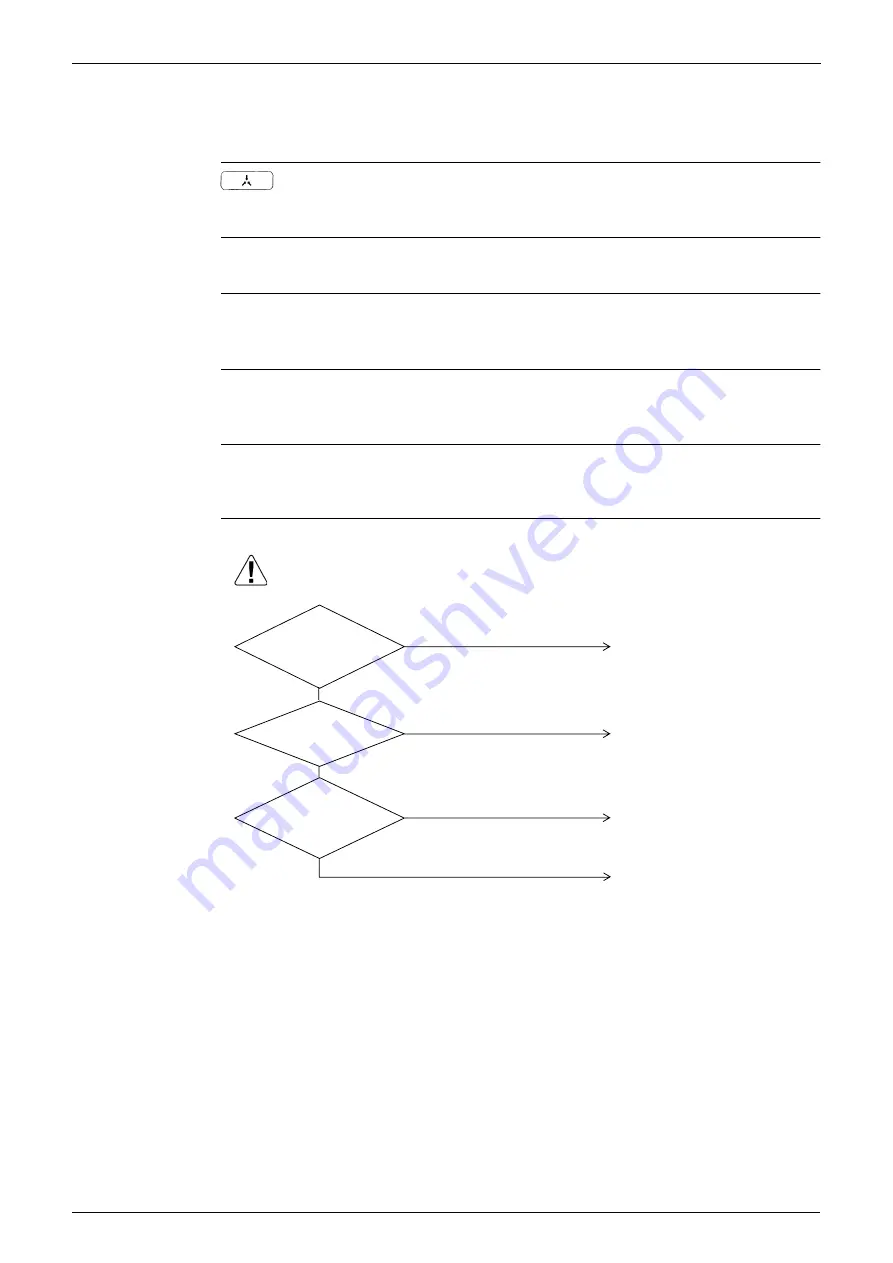
Troubleshooting
Caution
Be sure to turn off power switch before connect or disconnect connector,
or parts damage may be occurred.
(V2844)
Is the control
range setting switch
set correctly?
Is
the transmission
wiring disconnected or
wired incorrectly?
Replace the unified ON/OFF
controller.
Fix the wiring correctly.
Set by remote controller the
central control address for all
indoor units connected to the
central control line.
YES
YES
Set the control range setting
switch correctly and
simultaneously reset the power
supply for all optional controllers
NO
NO
NO
YES
Is the central
control address (group No.)
set for the
indoor unit?
Summary of Contents for VRV II RXYQ5MATL
Page 53: ...Specifications Si39 504 42 Specifications...
Page 115: ...Outline of Control Indoor Unit Si39 504 104 Function...
Page 161: ...Field Setting Si39 504 150 Test Operation...
Page 172: ...Si39 504 Troubleshooting by Remote Controller Troubleshooting 161...
Page 266: ...Si39 504 Piping Diagrams Appendix 255 RXYQ8MA 10MA 12MAYL E TL E 3D048033A...
Page 267: ...Piping Diagrams Si39 504 256 Appendix RXYQ14MA 16MAYL E TL E 3D048034A...
Page 271: ...Wiring Diagrams for Reference Si39 504 260 Appendix RXYQ8MA 10MA 12MAYL E 3D047088C...
Page 272: ...Si39 504 Wiring Diagrams for Reference Appendix 261 RXYQ14MA 16MAYL E 3D047089C...
Page 273: ...Wiring Diagrams for Reference Si39 504 262 Appendix 2 1 2 RXYQ MATL E RXYQ5MATL E 3D049059A...
Page 274: ...Si39 504 Wiring Diagrams for Reference Appendix 263 RXYQ8MA 10MA 12MATL E 3D049060A...
Page 275: ...Wiring Diagrams for Reference Si39 504 264 Appendix RXYQ14MA 16MATL E 3D049061A...
Page 283: ...Wiring Diagrams for Reference Si39 504 272 Appendix FXCQ40M 50M 80M 125MVE 3D039557A...
Page 285: ...Wiring Diagrams for Reference Si39 504 274 Appendix FXKQ25M 32M 40M 63MVE 3D039564B...
Page 289: ...Wiring Diagrams for Reference Si39 504 278 Appendix FXMQ40M 50M 63M 80M 100M 125MVE 3D039620B...
Page 290: ...Si39 504 Wiring Diagrams for Reference Appendix 279 FXMQ200M 250MVE 3D039621B...
Page 291: ...Wiring Diagrams for Reference Si39 504 280 Appendix FXHQ32M 63M 100MVE 3D039801D...
Page 292: ...Si39 504 Wiring Diagrams for Reference Appendix 281 FXAQ20M 25M 32MVE 40M 50M 63MVE 3D034206C...
Page 309: ...Selection of Pipe Size Joints and Header Si39 504 298 Appendix Note 1...
Page 315: ...Method of Replacing The Inverter s Power Transistors and Diode Modules Si39 504 304 Appendix...