


Si39-504
Field Setting
Test Operation
125
For setting items of (*1), refer to detailed information provided on page 136 onward.
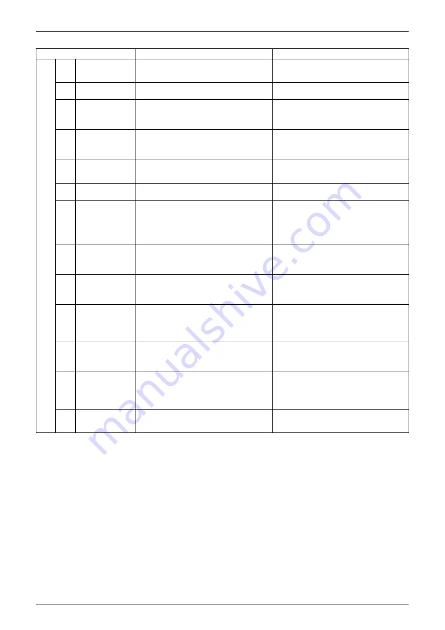
Setting item
Content and objective of setting
Overview of setting procedure
Serv
ic
e s
e
tti
ng
1
Indoor unit fan
forced H operation
Used to operate the indoor unit in the
stopped state in forced H operation mode.
Set No. 5 of "Setting mode 2" to indoor unit
forced fan H.
2
Indoor unit forced
operation
Used to operate the indoor unit in forced
operation mode.
Set No. 6 of "Setting mode 2" to indoor unit
forced operation mode.
3
Change of targeted
evaporating
temperature
(in cooling)
In cooling operation, used to change the
targeted evaporating temperature for
compressor capacity control.
Select high side or low side with No. 8 of
"Setting mode 2".
4
Change of targeted
condensing
temperature
(in heating)
In heating operation, used to change the
targeted condensing temperature for
compressor capacity control.
Select high side or low side with No. 9 of
"Setting mode 2".
5
Setting of defrost
selection
Used to change a temperature at which the
defrost operation is initiated, thus making
the initiation easy or hard.
Select fast side or slow side with No. 10 of
"Setting mode 2".
6
Setting of
sequential startup
Used to start units not in sequence but
simultaneously.
Set No. 11 of "Setting mode 2" to NONE.
7
Emergency
operation (*1)
If the compressor has a failure, used to
prohibit the operation of compressor(s)
concerned or outdoor unit(s) concerned
and to conduct emergency operation of the
system only with operable compressor(s)
or outdoor unit(s).
Make this setting while in "Setting mode 2".
For system with a single outdoor unit: Set
with No. 19 or 42.
For system with multiple outdoor units: Set
with No. 38, 39, or 40.
8
Additional
refrigerant
charging (*1)
If a necessary amount of refrigerant cannot
be charged due to the stop of outdoor unit,
operate the outdoor unit and then refill
refrigerant.
Set No. 20 of "Setting mode 2" to ON and
then charge refrigerant.
9
Refrigerant
recovery mode (*1)
Used to recover refrigerant on site.
With operations of indoor and outdoor units
prohibited, fully open the expansion valve
of the indoor and outdoor units.
Set No. 21 of "Setting mode 2" to ON.
10
Vacuuming mode
(*1)
Used to conduct vacuuming on site.
Fully open the expansion valves of the
indoor and outdoor units, and energize part
of solenoid valves. Use a vacuum pump to
conduct vacuuming.
Set No. 21 of "Setting mode 2" to ON.
11
ENECUT test
operation
Used to forcedly turn ON the ENECUT.
(Be noted this mode is not functional with
the indoor unit remote controller turned
ON.)
Set No. 24 of "Setting mode 2" to ON.
12
Power transistor
check mode
Used for the troubleshooting of DC
compressors.
Inverter waveform output makes it possible
to judge whether a malfunction results from
the compressor or the PC board.
Set No. 28 of "Setting mode 2" to ON.
13
Setting of model
with spare PC
board
In order to replace the PC board by a spare
one, be sure to make model setting.
For this setting, set the DS2-2, -3, and-4
switches on the PC board to the model
concerned.
Summary of Contents for VRV II RXYQ5MATL
Page 53: ...Specifications Si39 504 42 Specifications...
Page 115: ...Outline of Control Indoor Unit Si39 504 104 Function...
Page 161: ...Field Setting Si39 504 150 Test Operation...
Page 172: ...Si39 504 Troubleshooting by Remote Controller Troubleshooting 161...
Page 266: ...Si39 504 Piping Diagrams Appendix 255 RXYQ8MA 10MA 12MAYL E TL E 3D048033A...
Page 267: ...Piping Diagrams Si39 504 256 Appendix RXYQ14MA 16MAYL E TL E 3D048034A...
Page 271: ...Wiring Diagrams for Reference Si39 504 260 Appendix RXYQ8MA 10MA 12MAYL E 3D047088C...
Page 272: ...Si39 504 Wiring Diagrams for Reference Appendix 261 RXYQ14MA 16MAYL E 3D047089C...
Page 273: ...Wiring Diagrams for Reference Si39 504 262 Appendix 2 1 2 RXYQ MATL E RXYQ5MATL E 3D049059A...
Page 274: ...Si39 504 Wiring Diagrams for Reference Appendix 263 RXYQ8MA 10MA 12MATL E 3D049060A...
Page 275: ...Wiring Diagrams for Reference Si39 504 264 Appendix RXYQ14MA 16MATL E 3D049061A...
Page 283: ...Wiring Diagrams for Reference Si39 504 272 Appendix FXCQ40M 50M 80M 125MVE 3D039557A...
Page 285: ...Wiring Diagrams for Reference Si39 504 274 Appendix FXKQ25M 32M 40M 63MVE 3D039564B...
Page 289: ...Wiring Diagrams for Reference Si39 504 278 Appendix FXMQ40M 50M 63M 80M 100M 125MVE 3D039620B...
Page 290: ...Si39 504 Wiring Diagrams for Reference Appendix 279 FXMQ200M 250MVE 3D039621B...
Page 291: ...Wiring Diagrams for Reference Si39 504 280 Appendix FXHQ32M 63M 100MVE 3D039801D...
Page 292: ...Si39 504 Wiring Diagrams for Reference Appendix 281 FXAQ20M 25M 32MVE 40M 50M 63MVE 3D034206C...
Page 309: ...Selection of Pipe Size Joints and Header Si39 504 298 Appendix Note 1...
Page 315: ...Method of Replacing The Inverter s Power Transistors and Diode Modules Si39 504 304 Appendix...