


Test Operation
Si39-504
108
Test Operation
1.1.3
Check Operation
* During check operation, mount front panel to avoid the misjudging.
* Check operation is mandatory for normal unit operation.
(When the check operation is not executed, alarm code "U3" will be displayed.)
<Precautions for check operation>
•
If the check operation is started within approximately 12 minutes after turning ON the power
supply to the indoor and outdoor units, H2P will turn ON and the compressor will not
operate. Referring to information in table in 1.1.2 Turn Power On (on the previous page),
check to be sure the LED displays are normal and then operate the compressor.
•
For the outdoor-multi system, an outdoor unit to which the indoor unit connecting wires are
connected serves as the master unit. Be sure to make settings with pushbutton switches on
the master unit.
•
In order to ensure even refrigerant conditions, there may be cases where a maximum of
approximately 10 minutes are required for the compressor to start up, which, however, is not
a malfunction.
•
No malfunctions can be checked on individual indoor unit. After the completion of this check
operation, check the individual indoor unit for any malfunctions while in normal operation
mode using the remote controller.
•
While in check operation mode, the indoor units as well as the outdoor units start the
operation.
Do not attempt to conduct the check operation while working on the indoor unit.
•
Work with all the outside panels closed except for the switch box.
•
While in the test operation, operating sounds such as refrigerant passing sounds or solenoid
valve switching sounds may become louder.
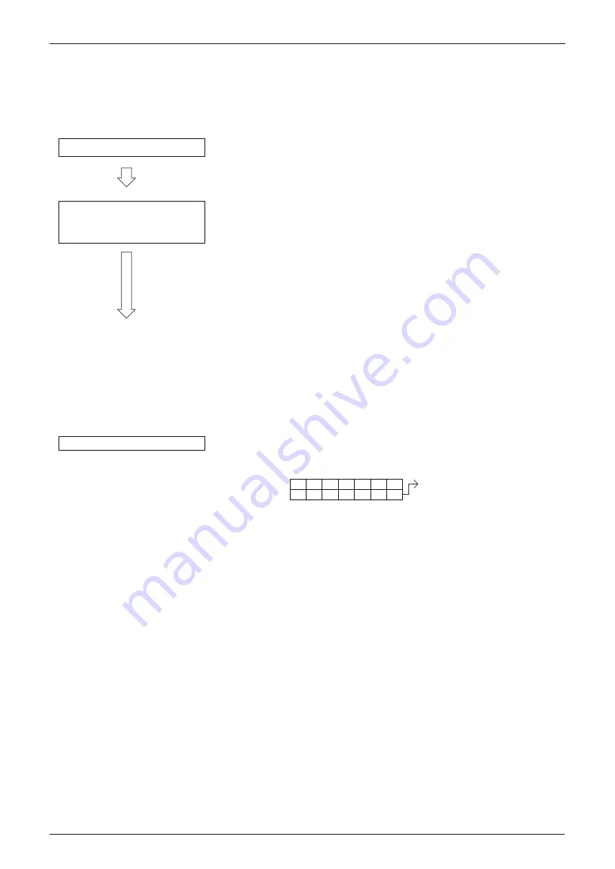
Completion of check operation
Press and hold the TEST
button (BS4) on outdoor unit
PC board for 5 seconds.
If the LED "H1P" turns OFF, the system is set to "Setting mode 1".
If the "H1P" turns ON or Blink, pressing the MODE button (BS1) will set
the system to "Setting mode 1".
¡
The test operation is started automatically.
The following judgements are conducted within 15 minutes.
2
"Check for wrong wiring"
2
"Check refrigerant for over charge"
2
"Check stop valve for not open"
2
"Pipe length automatic judgement"
*1. The "H2P" blinks during operation, and "TEST OPERATION" and
"UNDER CENTRALIZED CONTROL" are displayed on the remote
controller.
2. There may be cases where approximately 10 minutes are required
for the compressor to start up, which, however, is not a malfunction
but used to ensure even refrigerant conditions.
3. The check operation will be automatically conducted in cooling
mode.
4. In order to stop the compressor operation, press the RETURN
button (BS3). The compressor will stop after the completion of
residual operation for a period of approximately 30 seconds. (The
compressor operation cannot be stopped from the remote
controller.)
After the completion of check operation, check the operation results
through the LED displays.
Check Setting mode 1.
(For normal completion)
(For abnormal completion)
1
1
1
8
8
8
1
1
1
1
1
1
1
1
Check the malfunction code on
the remote controller and then
rectify the malfunction according
to information in the
"Troubleshooting".
Summary of Contents for VRV II RXYQ5MATL
Page 53: ...Specifications Si39 504 42 Specifications...
Page 115: ...Outline of Control Indoor Unit Si39 504 104 Function...
Page 161: ...Field Setting Si39 504 150 Test Operation...
Page 172: ...Si39 504 Troubleshooting by Remote Controller Troubleshooting 161...
Page 266: ...Si39 504 Piping Diagrams Appendix 255 RXYQ8MA 10MA 12MAYL E TL E 3D048033A...
Page 267: ...Piping Diagrams Si39 504 256 Appendix RXYQ14MA 16MAYL E TL E 3D048034A...
Page 271: ...Wiring Diagrams for Reference Si39 504 260 Appendix RXYQ8MA 10MA 12MAYL E 3D047088C...
Page 272: ...Si39 504 Wiring Diagrams for Reference Appendix 261 RXYQ14MA 16MAYL E 3D047089C...
Page 273: ...Wiring Diagrams for Reference Si39 504 262 Appendix 2 1 2 RXYQ MATL E RXYQ5MATL E 3D049059A...
Page 274: ...Si39 504 Wiring Diagrams for Reference Appendix 263 RXYQ8MA 10MA 12MATL E 3D049060A...
Page 275: ...Wiring Diagrams for Reference Si39 504 264 Appendix RXYQ14MA 16MATL E 3D049061A...
Page 283: ...Wiring Diagrams for Reference Si39 504 272 Appendix FXCQ40M 50M 80M 125MVE 3D039557A...
Page 285: ...Wiring Diagrams for Reference Si39 504 274 Appendix FXKQ25M 32M 40M 63MVE 3D039564B...
Page 289: ...Wiring Diagrams for Reference Si39 504 278 Appendix FXMQ40M 50M 63M 80M 100M 125MVE 3D039620B...
Page 290: ...Si39 504 Wiring Diagrams for Reference Appendix 279 FXMQ200M 250MVE 3D039621B...
Page 291: ...Wiring Diagrams for Reference Si39 504 280 Appendix FXHQ32M 63M 100MVE 3D039801D...
Page 292: ...Si39 504 Wiring Diagrams for Reference Appendix 281 FXAQ20M 25M 32MVE 40M 50M 63MVE 3D034206C...
Page 309: ...Selection of Pipe Size Joints and Header Si39 504 298 Appendix Note 1...
Page 315: ...Method of Replacing The Inverter s Power Transistors and Diode Modules Si39 504 304 Appendix...