


Installation manual
15
250B8W1B
Split system air conditioner
4PW25544-1A
Led state
Throughout the manual the state of the leds is indicated as follows:
x
OFF
w
ON
c
blinking
Setting the push button switch (BS1~5)
Function of the push button switch which is located on the outdoor
unit PCB (A1P):
Setting the mode 2
The set mode can be changed by pressing the
button for
5 seconds. The setting mode will change to setting mode 2 and the
H1P led will be ON
w
.
Exiting mode 2
When all settings are finished and the operation did start according to
the setting, push the
button once to exit the mode 2.
9.4.
Test operation
■
Check the stop valves
Make sure to open the gas and liquid line stop valves.
■
For details on test operation, refer to the indoor unit installation
manual.
Pre-run checks
1
Make sure the liquid and gas shut-off valves are open.
Be sure to close the frontside panel before operation, as not
doing so can cause electric shock.
-
The refrigerant pressure may not rise, even if the shut-off
valve is opened after an air purge is performed using a
vacuum pump.
This is because the indoor unit refrigerant piping is closed off
with electric valves inside. This will not create any problems
during operation.
2
To protect the compressor, make sure to turn on the power
supply 6 hours before starting operation.
Test operation from remote controller
1
Be sure to set it to cooling and press the operation switch.
2
Press the inspection/test-run switch on the remote control to put
the machine into test-run mode.
What to set with dip switch DS1
3
LOW NOISE OPERATION LEVEL SETTING (
)
(
= not installed = factory setting)
4
HIGH STATIC PRESSURE SETTING
5
AUTOMATIC LOW NOISE OPERATION AT NIGHT TIME
6
POWER CONSUMPTION LIMITATION SETTING (
)
1, 2, 7, 8
NOT APPLICABLE
DO NOT CHANGE THE FACTORY SETTING.
For changing the set mode
For field setting
For field setting
For test operation
For forced defrost or pump down
NOTE
If you get confused in the middle of the setting
process, push the
button once. Then it
returns to setting mode 2 (H1P led is ON
w
).
L.N.O.P
OFF
DEMAND
BS2
SET
BS1
MODE
BS3
RETURN
BS4
TEST
BS5
FORCED
DEF
H1P
H2P
H3P
H4P
H5P
H6P
H7P
MODE
TEST:
HWL:
HIGH STATIC
PRESSURE
LN.O.P
NGHT
L.N.O.P DEMAND
BS1 MODE
BS2 SET
BS3 RETURN
BS4 TEST
BS5 FORCED DEF
BS1 MODE
BS1 MODE
BS1 MODE
NOTE
After turning on the power supply, the unit cannot be
started until the H2P initialisation led goes off
(maximum 12 minutes).
Items to check
Electrical wiring
Inter-unit wiring
Ground wire
■
Is the wiring as mentioned on the wiring
diagram?
Make sure no wiring has been forgotten
and that there are no missing phases or
reverse phases.
■
Is the unit properly grounded?
■
Are any of the wiring attachment screws
loose?
■
Is the insulation resistance at least 2 M
Ω
?
-
Use a 500 V mega-tester when
measuring insulation.
-
Do not use a mega-tester for circuits
which are not 230 V.
Refrigerant piping
■
Is the size of the piping appropriate?
■
Is the insulation material for the piping
attached securely?
Are both the liquid and gas pipes
insulated?
■
Are the shut-off valves for both the liquid
side and the gas side open?
Extra refrigerant
■
Did you write down the extra refrigerant
and the refrigerant piping length?
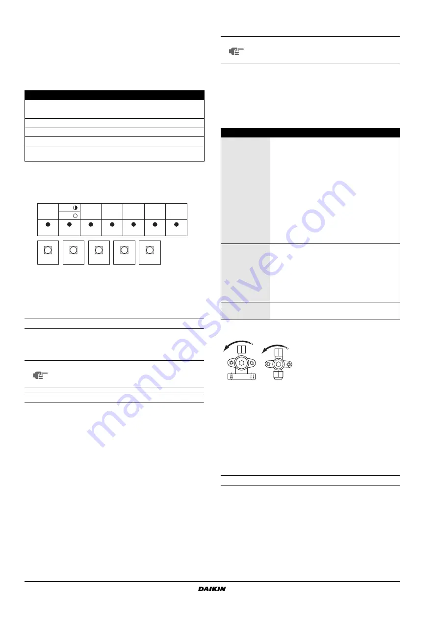
Opening direction
A
Liquid side
B
Gas side
Remove the cap and turn
counterclockwise with a
hex wrench until it stops
A
B


