


EWLD120~540MBYNN
Condenserless water-cooled water chillers
4PW22686-1
Installation manual
8
B
EFORE
STARTING
I do confirm having executed and checked all the above
mentioned items.
Keep for future reference.
C
USTOMIZATION
IN
THE
SERVICE
MENU
To change a setting in the service menu:
1
Enter the usersettings menu as indicated in the operation
manual and press the
h
key to go to the last screen to enter the
service menu (this is only possible if the unit is off).
2
Enter the correct password using the
h
and
g
keys. The
password can be found in the service manual.
3
Press
q
to confirm the password and enter the service menu.
4
Go to the screen which contains the parameter to be modified by
using the
h
and
g
keys.
5
Position the cursor behind the parameter to be modified using
the
q
key.
6
Select the appropriate setting using the
h
and
g
keys.
7
Press
q
to confirm the modification. When the modification has
been confirmed, the cursor switches to the next parameter
which can now be configured.
8
Place the cursor in the top left corner of the screen when you
are finished changing the parameters on this screen.
9
Repeat from instruction 4 onwards to modify other parameters.
Setting of the minimum outlet water temperature
It is possible to change the minimum outlet water temperature
(
) in the service menu. Before lowering the minimum
outlet water temperature:
■
Make sure that sufficient glycol is added to the water system
according to the table.
■
Make sure that the low pressure safety is lowered according to
the table.
Defining a unit in a setup of a DICN system
Change the setting of
to
on each unit.
Setting the password for safety reset
To avoid resetting of safeties by unqualified persons, the user
password is asked by default when resetting a sefety.
This password however can be changed to
or to
.
Setting of compressor running hours
When the displayed running hours do not comply with the actual
running hours of the compressor it is possible to change the running
hours to comply.
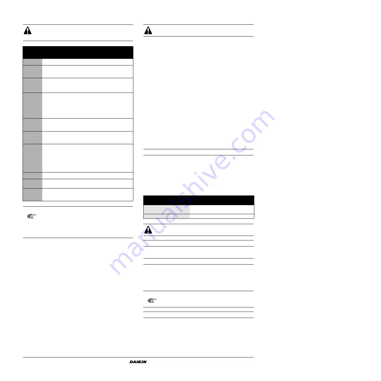
The unit should not be started, not even for a very short
period of time, before the following pre-commissioning
checklist is filled out completely.
tick
✓
when
checked
standard steps to go through before
starting the unit
■
1
Check for external damage
■
2
Open all shut-off valves indicated by a red label: "OPEN THIS
VALVE BEFORE OPERATION". (Open the liquid line, dis-
charge and suction (if provided) stop valves completely.)
■
3
Install mainfuses, earth leak detector and mainswitch.
Recommended fuses: aM according to IEC standard 269-2.
Refer to the wiring diagram for size.
■
4
Supply the main voltage and check if it is within the allowable
±10% limits of the nameplate rating.
The electrical main power supply should be arranged so, that
it can be switched on or off independently of the electrical
supply to other items of the plant and equipment in general.
Refer to the wiring diagram, terminals L1, L2 and L3.
■
5
Supply water to the evaporator and verify if waterflow is within
the limits as given in the table under
■
6
The piping must be completely purged. See also chapter
"Preparing, checking and connecting the water circuit" on
page 4
■
7
Connect the pump contact(s) in series with the contact of the
flowswitch(es), so that the unit can only come in operation
when the waterpumps are running and the water flow is
sufficient.
For DICN configurations, every chiller shall have its own
flowswitch and shall be interlocked with the pump from which it
gets the flow.
■
8
Check the oil level in the compressors.
■
9
Install the filter kit(s) supplied with the unit in front of the
evaporator(s) water inlet.
■
10
Check that all the water sensors are correctly fixed into the
heat exchanger (see also the sticker attached to the heat
exchanger).
NOTE
■
It is necessary to read the operation manual
delivered with the unit before operating the unit. It
will contribute to understand the operation of the
unit and its electronic controller.
■
Close all switch box doors after installation of the
unit.
Date
Sign
All customized settings must be done by a licensed
technician.
minimum outlet water (
)
2°C
0°C
–5°C
–10°C
Weight of ethylene glycol
(%)
10
20
30
40
Weight of propylene glycol (%)
15
25
35
40
Low pressure setting
(bar)
0.8
0.6
0.2
0.2
Improper setting of the minimum outlet water temperature
can result in severe damage of the equipment.
NOTE
Since inadequate resetting of safeties can damage the
machine, it is advised to keep the default setting of
.


