background image


GB 


6. 

PREPARING FOR WELDING 


6.1.  Mains connection 


Varmig  191  Supermig  welding  machines  are  equipped  with  connection  for  1  x  400V/50Hz  and 
230V/50Hz. At connection to 230 V mains supply use the appropriate adapter enclosed. 


Please  assure,  that  the  main  switch  is  in  position 

0

  before  connecting  the  cable  to  the  plug 

socket.  


6.2    Mounting the wire spool 


Mount  the  wire-spool  (low  alloyed  steel)  onto  the  spool  holder.  Please  pay  attention  to  the  correct 
direction of unwinding the wire by mounting the spool. 


6.3    Leading-trough  the wire 


The  wire  has  to  be  bend  before  leading  it  trough  the  feeding  rollers  and  infeed  tube  of  welding  torch  to 
avoid sticking. With turning  the screw to the left release the spring and shift up the clamping handle with 
the  braking-roller.  Assure,  that  the  groove  on  the  feeding-roller  is  equal  to  the  welding  wire  diameter. 
Insert the wire trough the infeed tube  of the roller drive and a few cm into the infeed tube of the welding 
torch. Adjust the appropriate pressure of the feeding roller with turning the screw to the right (the feeding 
roller may not slide on the wire). 


6.4    Gas cylinder  


place the gas-cylinder onto the backside of the machine (max 20 kgs) or floor 


fix the gas-cylinder in place with safety chain 


N.B.! The cylinder will only be optimally fixed in the upper part of the cylinder (not at the neck) 


remove the protective cap from the gas cylinder 


give the gas-cylinder valve a brief turn to the left (anticlockwise) to blow off any dirt around the valve 


check the seal on the pressure regulator 


screw the pressure regulator onto the gas cylinder and tighten it 


assure, that no gas deserts 


attach the protective-gas hose to the gas-pipe on the machine and fix it with enclosed embrace 


7. 

MIG/MAG WELDING 


                  CAUTION!

  Before starting up for the first time read the safety rules. 


place the machine onto the working place so, that the best cooling possibility is achieved  


plug the machine into the mains  


set the protective-gas rate  


fix the welding cable onto the central connector on the front of the machine 


connect the earth (mass) cable to the work piece 


adjust the wire speed with a knob approximately into the middle of the scale 


check out if the wire is leaded-trough correctly  


remove the protective gas-nozzle and the contact nozzle from the torch 


assure, that the chosen contact nozzle is equal to the wire diameter 


press the button on the torch and check the  wire feed and the gas outflow. If everything is OK, the 

wirefeeder is pushing-out the wire and the gas valve is open, so the das is coming out 


fix the protective gas-nozzle and the contact nozzle back  to the torch 


the perfect length of the welding wire outside the nozzle is 5-10 mm (cut off the rest) 


depending materials you are intended to weld, choose the suitable parameters with a welding 

current-switch and wirespeed-knob 


try  to  weld  by  pressing  the  button  on  the  torch.  If  the  chosen  parameters  are  correct  the  sound  of 

welding is equable and the seam is well. 


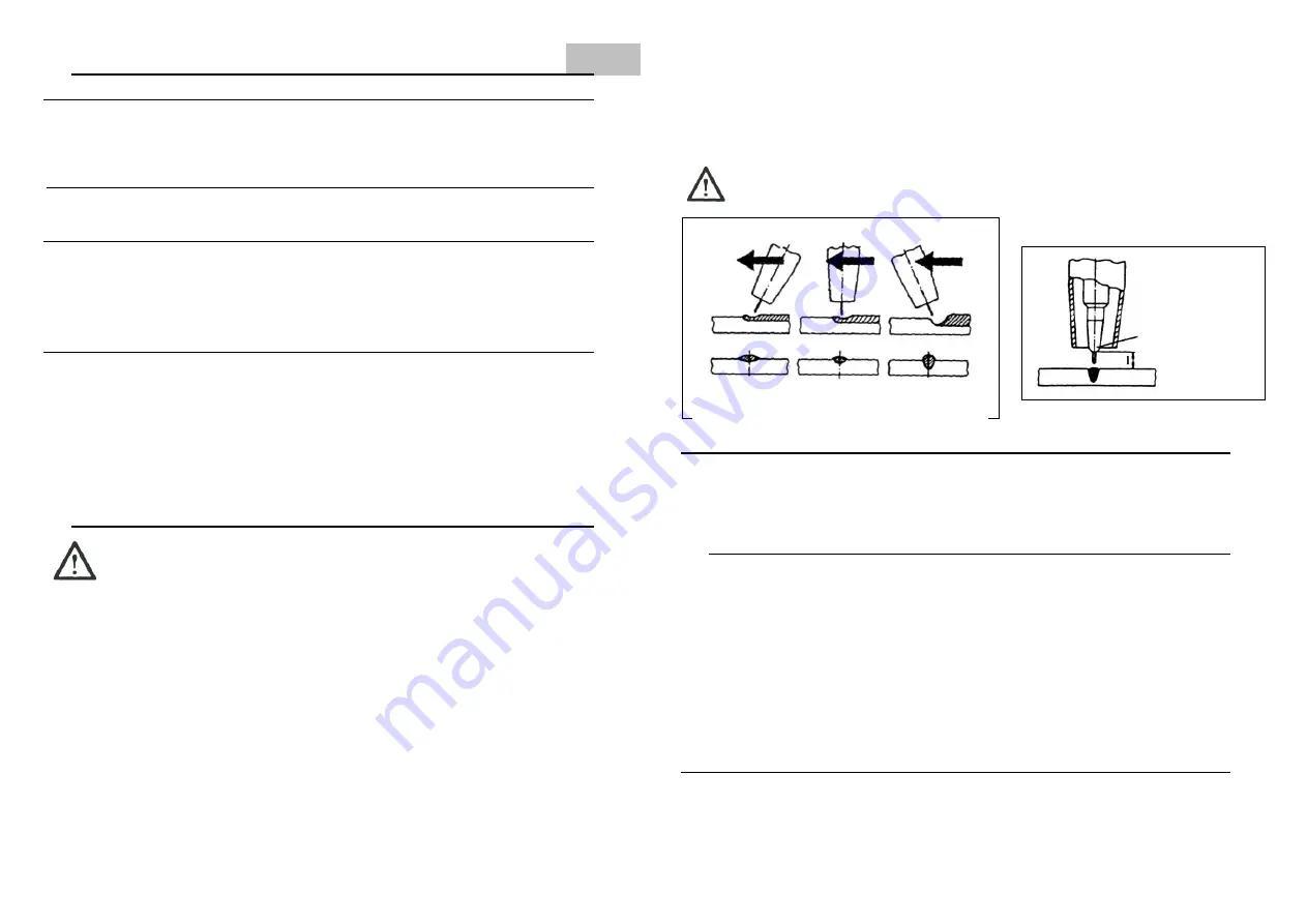
The  stable arc is  very  important for  quality  welding-seam.  Please  pay  attention to  the  constant  distance 
between  nozzle  and  work  piece  and  try  to  guide  the  torch  as  constantly  as  possible.  The  appropriate 
distance between torch and work piece is around 5-10 mm (stainless steel) and 20 mm (aluminium).  


The machine is equipped with an over temperature thermostat. If this is active, the orange indicator is lit 
up. At that moment the machine is out of order. The cooling system operates only. The machine will fail to 
weld until temperature indicator is lit up.  


                 Caution! DON'T SHUT OFF THE MACHINE IF TEMPERATURE INDICATOR IS LIT UP!  


CONTACT 


NOZZLE        


PUSH             RECTANGULAR          PULL 

              POSITION              POSITION           POSITION 


7.1.   Aluminium welding 


For welding of Aluminium as protective gas only pure Argon can be used. For welding of Aluminium the 
wirefeeding rollers with »V« groove are to be changed with rollers with »U« groove. Also the spiral infeed 
tube on the wirefeeding mechanism is to be changed with a Teflon infeed tube 

 2/4, l-90 mm long. We 

also suggest to replace the usually welding cable with a  short welding cable (1,5 m) with a teflon infeed 
tube to avoid sticking and bending of wire. 

 
8. 

CARE AND MAINTENANCE 


Warning!

  Before opening the machine, switch it off, unplug it from the mains and put up the warning sign 

to  stop  anybody  inadvertently  switching  it  back  on  again.  If  necessary,  discharge  the  electrolytic 
capacitors. 
 
In order to keep your welding machine operational for years to come, you should observe the following: 


carry out safety inspections at the stipulated intervals 


depending on the machine location, but no less often than twice a year, remove the side panels from 

the machine and blow the inside of the machine clean with dry, reduced blow compressed air. Do not 
aim air-jets at electronic components from to close a range. 


If a lot of dust has accumulated, clean the cooling-air ducts. 


daily  check  out  the  nozzles,  wirefeeder  and  rollers,  hose,  torch,  pressure  regulator  and  clean  or 

replace it if necessary  


weekly check out the cables, plugs and replace it if necessary 


9.   AFTER-SALES SERVICES AND WARRANTY 


Please refer to the Warranty (Indemnity) bond! 


Summary of Contents for VARMIG 191 Supermig

Page 1: ...rjenje in rezanje ter robotizacija d d Industrijska ulica 4 SLO 9220 Lendava Tel fax E mail url 386 0 2 5788 820 386 0 2 5751 277 info varstroj si http www varstroj si Prodaja Export Servis tel Servis...

Page 2: ...ja vodi do izgube energije in eventualno do razelektrenja Uporabljeni kabli ne smejo le ati v bli ini verige dvi ne vrvi elektri nih vodov ali jih kri ati 4 Izogibajte se uporabi aparata v mokrih pro...

Page 3: ...ogiji varjenja Prednosti varjenja po postopku MIG MAG z aparati VARMIG Supermig racionalnej e varjenje manj i stro ki ob veliki hitrosti varjenja in irokem podro ju uporabe enostavno rokovanje mo nost...

Page 4: ...za maso Cevni paket z varilno pi tolo vstavimo v centralni priklju ek Nato obra amo plasti no matico v desno tako dolgo dokler ne za utimo odpora A tem je cevi paket montiran na svoje mesto Kabel s ma...

Page 5: ...dilo 2 Izpihati spiralno vodilo 3 O istiti lindro znotraj plinske obe z zagozdo iz lesa ali plastike Nastale lindre se brez te av odstranijo e predhodno po kropimo plinsko obo z topilom na bazi siliko...

Page 6: ...nalna lu ka in ventilator deluje vendar pa ob pritisku tipke gorilnika ni mo no variti ne izstopa varilna ica Po kodba tipke gorilnika ali masnega priklju ka Zamenjati tipko gorilnika ali cevnega pake...

Page 7: ...olgenden genannten Vorschriften einzuhalten 1 1 Anschluss des Schweissger tes Hierzu folgende Vorschriften unbedingt beachten 1 Anschluss und Wartung des Ger tes m ssen gem der beim Anwender geltenden...

Page 8: ...wurde f r ziehen und Transportieren entworfen und gebaut Werden folgende Regeln eingehalten so ist ein Transportieren einfach m glich 1 Das Ger t kann am darauf befindlichen Griff gezogen werden nachd...

Page 9: ...u h ren 5 Anzeige und Beschreibung der Funktionen der Ger te Varmig 191 Supermig Bild 5 Frontplatte Varmig 191 Supermig Pos Bezeichnung Funktion 01 Umschalter Schalter zum Ein Ausschalten des Ger tes...

Page 10: ...e wird der entsprechende Drahtdurchmesser gew hlt 0 6 0 8 mm siehe technische Daten Nach der Auswahl 230V oder 400V ist das Schwei ger t eingeschaltet und zum Schwei en bereit Mittels Stufenschalter d...

Page 11: ...Thermostat das Ger t abgeschaltet die gelbe Lampe leuchtet Das Ger t wird nach der Abk hlung wieder eingeschaltet die gelbe Lampe leuchtet nicht W HREND DER K HLUNG DAS GER T NICHT AUSSCHALTEN Schlech...

Page 12: ...ear safety glass with side shield particularly during manual or mechanical removal of slag High temperature slag may be projected to great distances Pay attention to fellow workers in the vicinity 5 P...

Page 13: ...ntended to be used SOLELY for MIG MAG welding Any other use or any use going beyond the above is deemed to be not for the intended purpose and the manufacturer shall not be liable for any damage resul...

Page 14: ...e ON 230 400V and OFF 02 Step switch Regulation of voltage current welding 03 Potentiometer Setting the welding wire feeding speed 0 to 18 m min 04 Potentiometer for setting the spot welding time Spot...

Page 15: ...the wirefeeder is pushing out the wire and the gas valve is open so the das is coming out fix the protective gas nozzle and the contact nozzle back to the torch the perfect length of the welding wire...

Page 16: ...he mass clamp and the work piece Clean the point of contact check and tighten the earthening connection Incorrect welding current selected Select the appropriate welding current refer to this operatin...

Page 17: ...izni kell s elt vol tani a meghib sod sokat A villamos k sz l keket id nk nt ellen rizni kell K belt csak elegs ges tmetszettel haszn ljon 3 A kontaktk belt min l k zelebb kell a munkdarabhoz csatolni...

Page 18: ...hat s gi szempontb l K l n felt ntend tulajdons gai a VARMIG 191 Supermig nek a k vetkez k racion lisabb hegeszt s alacsonyabb k lts gek magas hegeszt si gyorsas g s sz les haszn lati k r egyszer m k...

Page 19: ...ez s egy mechanizmusb l a hozzatartoz hajt g rg vel s egy huzalnyom g rg vel melynek nyom erej t egy csavaron elhelyezked csavarrug val lehet be ll tani 4 10 Magneses g zszelep A v d g z nyit s t s el...

Page 20: ...a hegeszt h zal gyenge h z s s n l a t rcsa el tud fordulni A f kez s nem szabad hogy tul er s legyen mert azzal a hajt motor feleslegesen tulterhel dik A hegeszt h zal t rol t rcsa felrak s n l figy...

Page 21: ...izni a szekunder s primer vezet kek csatlakoz s t 9 J T LLAS S SZERV Z N zd a j t ll si jegyet 10 ALKATR SZJEGYZ K bra Poz Le r s VARMIG 191 Supermig Jegyzetek 1 1 Kapcsol 230 0 400 696620 1 2 Ellen r...

Page 22: ...titani kicser lni a spir lvezet t Nem megfelel kiv lasztott h zaltov bit ker k K v lasztani a megfelel kereket az tm ret l f gg en Nem el gs ges h t s Megs r lt a ventil tor Kicser lni a ventil tort A...

Page 23: ...ara i lindre Vru a lindra i iskrice prskaju a talina predstavljaju uzrok po ara Po ar i eksplozije mo emo sprije iti ako se dr imo odgovaraju ih propisa Udaljite zapaljive predmete ili ih pokrijte sa...

Page 24: ...e to kanja 0 5 2 sek Promjer ice 0 6 0 8 mm Razred izolacije IP21S Hla enje ventilator Masa 40 kg Dimenzije xDxV mm 733x430x640 4 KONSTRUKCIJA Poluautomat VARMIG 191 Supermig je zavariva ki aparat za...

Page 25: ...5 8 Elementi za upravljanje strojem za zavarivanje glavna sklopka potenciometar za regulaciju brzine dodavanje ice priklju ni kabel kabel za masu sa klije tama cijevni paket sa gorionikom za zavarivan...

Page 26: ...niku uklju i se rad stroja motor po inje dodavati icu koja se dotakne materiala i uspostavi se elektri ni krug i elektri ni luk Gorionik za zavarivanje pomjeramo u jednom od smjerova koji su prikazani...

Page 27: ...d rada prestao zavarivati Termostat je zbog temperaturnog preoptere enja isklju io uto svijetlo zasvijetli Aktivno je jedino hla enje ventilatorom Pustiti da se stroj ohladi Termostat e automatski ukl...

Page 28: ...re nika 3 Kabel za masu pri vrstiti na predmet zavarivanja to bli e radnom mestu Njegovo priklju enje na nosa gra evinske konstrukcije ili daleko od radne povr ine vodi do gubitka energije Upotrebljen...

Page 29: ...rata dim vatru ako se pojave udni zvuci i vibracije kod rada aparata isklju ite ga i izvucite utika iz napona U tim slu ajevima potreban je stru an pregled aparata Ako do e do izpada napona ili ako se...

Page 30: ...nje i zatvaranje za titnog gasa Kad se ne zavaruje dovod gasa je zatvoren a prilikom zavarivanja on se otvara i kroz cijevni paket i gorionik prolazi za titni gas Ako je sve u redu uz pritisak prekida...

Page 31: ...e Potenciometar za regulaciju brzine dodavanja ice za zavarivanje okrenemo u sredi nji polo aj Proverimo da li je ica uvedena preko mehanizma za dodavanje u spiralu cevnog paketa Sa gorionika odvijemo...

Page 32: ...gme potenciometra 690229 1 6a Poklopac dugmeta FI23 690230 1 07a Cev ica 603447 1 7 Priklju ak centralni kpl 603446 1 8 Uti nica komplet 691051 1 9 Kota 160 680607 1 10 Kapa za titna 680609 1 11 Osovi...

Page 33: ...NJA U slu aju da do e do zastoje iz uzroka koji nije opisan u gornjoj tabeli zovite najbli i servis VA NO Ovoj prira nik za upotreba e napi an za iskusni korisnici Pred upotreba na aparatot detalno pr...

Page 34: ...a kade se zavaruva potrebno e da se osigura so yid otporen na po ar zatoa to iskrite i zgurot mo e da gi zagrozat licata vo blizina 1 3 Spre uvawe na po ar Vrelata zgura i iskri pretstavuvaat pri ina...

Page 35: ...akot 4 1 Ku i te na poluavtomatot Izraboteno e od visoko kvaliteten materijal moderno dizajniran taka da mo e bez golem napor ednostavno i lesno da se zameni koturot so ica a istovremeno i lesno se od...

Page 36: ...namestete go reduktorot Ako te e plinot reduktorot pove e pati odvrtete go i povtorno zavrtete go Na priklu okot za plin montirajte armirana cevka za plin i spojte go so sigurnosniot ventil na aparat...

Page 37: ...uja Site servisni raboti na aparatot dozvoleno e da gi izveduvaat samo stru ni lica 9 GARANCIJA I SERVIS 10 SPISOK NA REZERVNI DELOVI Slika Poz ime VARMIG 191 Supermig 1 1 Prekinuva 230 0 400 696620 1...

Page 38: ...VIS Da se zameni mehanizmot za dodavawe na ica Nema struja na zavaruvawe O teten e cevniot paket gorilnikot ili masa kabelot O teten e prekinuva ot na gorilnikot Da se proveri ili zameni o teteniot ka...

Page 39: ...APPENDIX D 1 Disposal of the device after its service life The appliance contains electronic components that need to be disposed of properly and materials that need to be recycled When packaging we u...

Reviews: