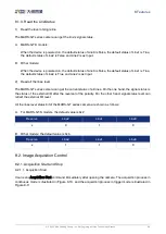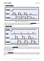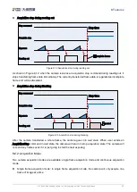
7.Electrical Interface
© 2023 China Daheng Group, Inc. Beijing Image Vision Technology Branch 47
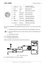
4
POWER_IN
Purple
Camera external power
12V (-10%) ~ +24V (+10%)
5
Line2
Orange
GPIO input/output
6
RS232 Rx
Pink
RS232 serial port receiving*
7
Line1-
White Green
Opto-isolated output -
8
Line1+
White Blue
Opto-isolated
9
GND
White Grey
PWR GND & GPIO GND
10
GND
White Purple
PWR GND & GPIO GND
11
POWER_IN
White Orange
Camera external power
12V (-10%) ~ +24V (+10%)
12
RS232 Tx
White Pink
RS232 serial port sending*
Table 7-2 I/O port definition (back sight of camera)
The input power of MARS-GT series digital camera must be 12V (-10%) ~ 24V (+10%) when powered by
I/O port.
1)
The polarity of power cannot be reversed, otherwise, camera or other peripherals could burn out.
2)
The polarity of GPIO pins cannot be reversed, otherwise, camera or other peripherals could
burn out.
3)
*Available for some models.
7.3.2.
I/O Electrical Characteristics
7.3.2.1.
Line0 (Opto-isolated Input) Circuit
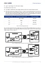
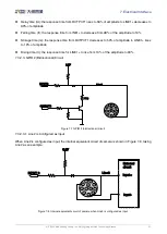
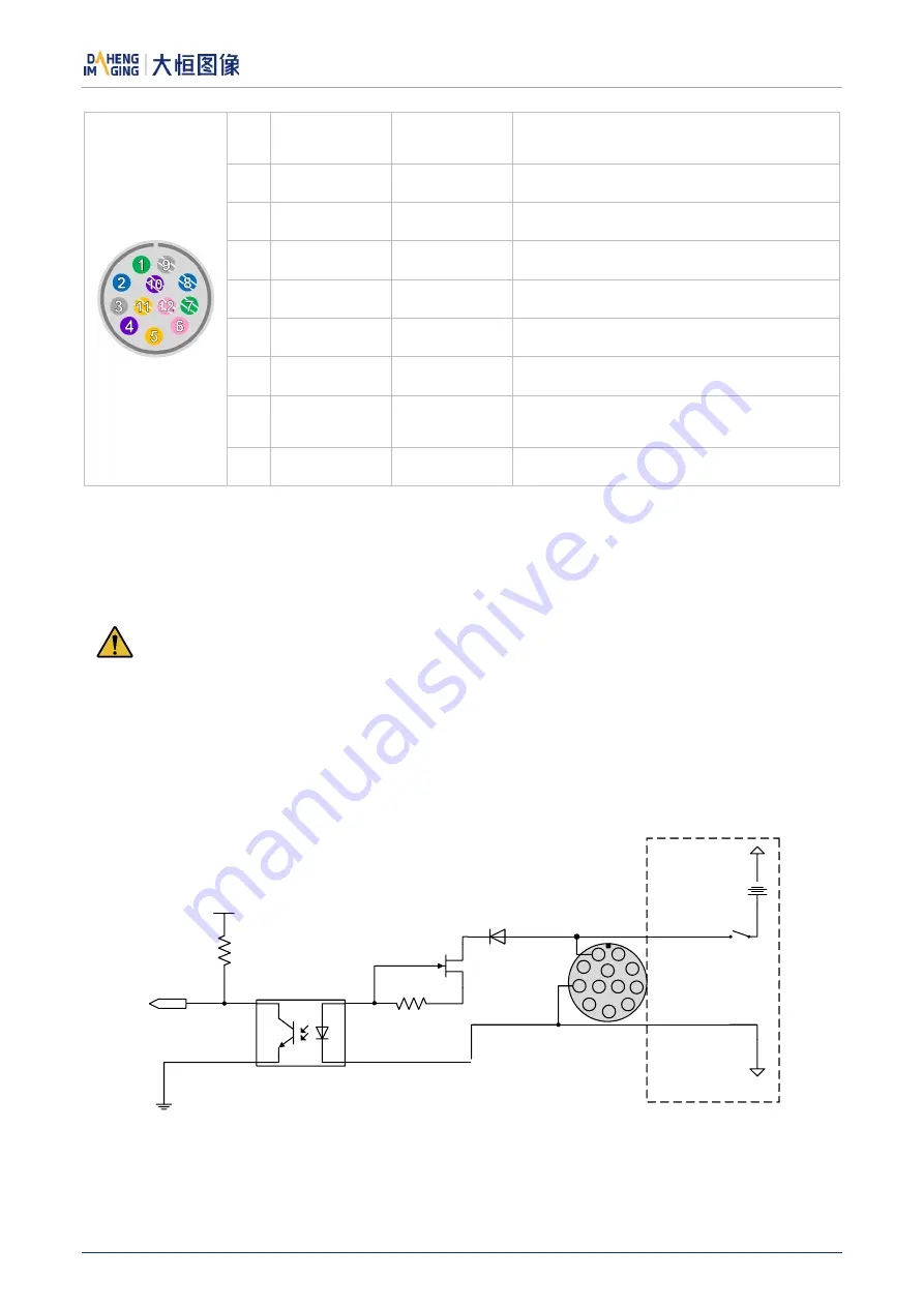
Hardware schematics of opto-isolated input circuit is shown as Figure 7-1.
3.3V
Line 0+
Line 0-
INPUT 0
5V-24V
9
1
2
3
4
5
6
7
8
12
11
10
External circuit
Figure 7-1 Opto-isolated input circuit
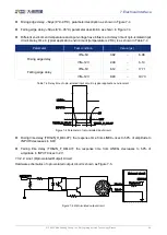
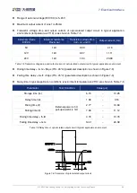
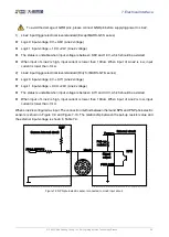
Logic 0 input voltage: 0V~+2.5V (Line0+ voltage)

