background image

DGS-1510 Series Gigabit Ethernet SmartPro Switch Web UI Reference Guide 

320 

The under attack state have three modes: drop, block, and shutdown. A BPDU protection enabled port 
will enter an under attack state when it receives one STP BPDU packet and it will take action based on 
the configuration. Thus, BPDU protection can only be enabled on the STP-disabled port. 

BPDU protection has a higher priority than the FBPDU setting configured by configure STP command in 
the determination of BPDU handling. That is, when FBPDU is configured to forward STP BPDU but BPDU 
protection is enabled, then the port will not forward STP BPDU. 

BPDU protection also has a higher priority than the BPDU tunnel port setting in determination of BPDU 
handling. That is, when a port is configured as BPDU tunnel port for STP, it will forward STP BPDU. But if 
the port is BPDU protection enabled. Then the port will not forward STP BPDU. 


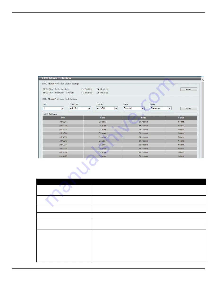
To view the following window, click 

Security > BPDU Attack Protection

, as shown below: 


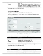
Figure 9-62 BPDU Attack Protection window 


The fields that can be configured are described below: 

Parameter 

Description 

BPDU Attack Protection State 

Select to enable or disable the BPDU attack protection feature’s global 
state here. 

BPDU Attack Protection Trap 
State 

Select to enable or disable the BPDU attack protection feature’s trap 
state here. 

Unit 

Select the switch unit that will be used for this configuration here. 

From Port / To Port 

Select the appropriate port range used for the configuration here. 

State 

Select to enable or disable the BPDU attack protection feature’s state 
on the port(s) specified. 

Mode 

Select the BPDU attack protection feature’s mode that will be applied 
to the port(s) specified. Options to choose from are 

Drop

Block

 and 

Shutdown

.  

Drop

 – Drop all received BPDU packets when the port enters under 

attack state. 

Block

 – Drop all packets (include BPDU and normal packets) when the 

port enters under attack state. 

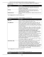
Summary of Contents for DGS-1510 Series

Page 1: ...1...

Page 2: ...ks used in this text D Link and the D Link logo are trademarks of the D Link Corporation Microsoft and Windows are registered trademarks of the Microsoft Corporation Other trademarks and trade names m...

Page 3: ...9 System Information Settings 9 Peripheral Settings 10 Port Configuration 11 Port Settings 11 Port Status 12 Port Auto Negotiation 13 Error Disable Settings 14 Jumbo Frame 15 PoE DGS 1510 28P Only 16...

Page 4: ...nt Settings 46 Telnet Web 47 Session Timeout 48 DHCP 49 Service DHCP 49 DHCP Class Settings 49 DHCP Relay 51 DHCPv6 Relay 56 DHCP Auto Configuration 58 DNS 58 DNS Global Settings 59 DNS Name Server Se...

Page 5: ...asic TLVs Settings 129 LLDP Dot1 TLVs Settings 130 LLDP Dot3 TLVs Settings 131 LLDP MED Port Settings 132 LLDP Statistics Information 133 LLDP Local Port Information 134 LLDP Neighbor Port Information...

Page 6: ...Map 271 ACL VLAN Filter 273 9 Security 275 Port Security 275 Port Security Global Settings 275 Port Security Port Settings 276 Port Security Address Entries 277 802 1X 278 802 1X Global Settings 283 8...

Page 7: ...tion 332 Guest VLAN 332 Network Access Authentication Global Settings 333 Network Access Authentication Port Settings 335 Network Access Authentication Sessions Information 336 Safeguard Engine 337 Sa...

Page 8: ...Firmware Upgrade Backup 371 Firmware Upgrade from HTTP 371 Firmware Upgrade from TFTP 372 Firmware Backup to HTTP 372 Firmware Backup to TFTP 373 Configuration Restore Backup 373 Configuration Restore...

Page 9: ...allation Guide DGS 1510 Series Gigabit Ethernet SmartPro Switch CLI Reference Guide Conventions Convention Description Boldface Font Indicates a button a toolbar icon menu or menu item For example Ope...

Page 10: ...Pro Switch Web UI Reference Guide 2 NOTICE A notice indicates either potential damage to hardware or loss of data and tells you how to avoid the problem CAUTION A caution indicates a potential for pro...

Page 11: ...agent decodes the incoming SNMP messages and responds to requests with MIB objects stored in the database The SNMP agent updates the MIB objects to generate statistics and counters Web based Managemen...

Page 12: ...onfigured on this switch When connecting to the Web UI for the first time simply leave the User Name and Password fields blank and click the Login button Smart Wizard After a successfully connecting t...

Page 13: ...ess settings from a DHCP server IP Address Enter the IP address of the Switch here Netmask Select the Netmask option here Gateway Enter the default gateway IP address here Tick the Ignore the wizard n...

Page 14: ...isable the SNMP function Tick the Ignore the wizard next time option to skip the Smart Wizard on the next login Click the Exit button to discard the changes made exit the Smart Wizard and continue to...

Page 15: ...account Password Type Select the password type here Options to choose from are None Plain Text and Encrypted Password After selecting either Plain Text or Encrypted as the Password Type this field wil...

Page 16: ...s and subfolders contained within them to display windows AREA 2 Presents a graphical near real time image of the front panel of the Switch This area displays the Switch s ports and expansion modules...

Page 17: ...ow the Device Information CPU and Used status are displayed It appears automatically when you log in the Switch To return to the Device Information window after viewing other windows click the DGS 151...

Page 18: ...Apply button to accept the changes made Peripheral Settings This window is used to configure the environment trap settings and environment temperature threshold settings To view the following window...

Page 19: ...r the low threshold value of the warning temperature setting The range is from 100 to 200 Celsius degree Tick the Default check box to return to the default value Click the Apply button to accept the...

Page 20: ...re This option will manually force the connected on the selected port to only connect at the speed specified here Options to choose from are Auto 10M 100M 1000M 1000M Master 1000M Slave and 10G The Sw...

Page 21: ...n be configured are described below Parameter Description Unit Select the switch unit that will be used for this configuration here Port Auto Negotiation This window is used to view detailed port auto...

Page 22: ...bed below Parameter Description Unit Select the switch unit that will be used for this configuration here Error Disable Settings This window is used to configure the sending of SNMP notifications for...

Page 23: ...are described below Parameter Description ErrDisable Cause Select the error disable causes here Options to choose from are All Port Security Storm Control BPDU Attack Protection Dynamic ARP Inspectio...

Page 24: ...A whereby power is sent out over pins 1 2 3 and 6 The Switches work with all D Link 802 3af capable devices The Switch includes the following PoE features Auto discovery recognizes the connection of...

Page 25: ...the disconnection of PD which in power provisioned with lower priority in order to release the power to the new connected PD with higher priority under power shortage conditions Trap State Select thi...

Page 26: ...t Select the appropriate port range used for the configuration here Description Enter the text that describes the PD connected to a PoE interface The maximum length is 32 characters Click the Delete D...

Page 27: ...Never Max Wattage When selecting Auto in the Mode drop down list this option appears Tick the check box and enter the maximum wattage of power that can be provisioned to the auto detected PD If the va...

Page 28: ...Description Unit Select the switch unit that will be used for this configuration here Click the Clear All button to clear PoE statistics for all ports Click the Clear button to clear the PoE statistic...

Page 29: ...fields that can be configured are described below Parameter Description Unit Select the switch unit that will be used for this configuration here PoE LLDP Classification This window is used to display...

Page 30: ...s that can be configured are described below Parameter Description Unit Select the switch unit that will be used for this configuration here System Log System Log Settings This window is used to view...

Page 31: ...ings 5 Notifications 6 Informational and 7 Debugging Discriminator Name Enter the discriminator name used here This name can be up to 15 characters long Write Delay Enter the interval for periodic wri...

Page 32: ...to choose from are Drops and Includes Severity Select the severity behavior option and the value of the type of information that will be logged Behavior options to choose from are Drops and Includes S...

Page 33: ...fications 6 Informational and 7 Debugging Facility Select the facility value here Options to choose from are 0 to 23 Discriminator Name Enter the discriminator name here This name can be up to 15 char...

Page 34: ...vices organize the SNTP subnet of servers and clients and adjust the system clock in each participant Clock Settings This window is used to configure the time settings for the Switch To view the follo...

Page 35: ...configure the summer time that should start and end on the specified date of the specified month Time Zone Select to specify your local time zone s offset from Coordinated Universal Time UTC The field...

Page 36: ...nth Select date of the month that summer time will end To Month Select the month that summer time will end To Year Enter the year that the summer time will end To Time HH MM Select the time of the day...

Page 37: ...Time Range window The fields that can be configured are described below Parameter Description Range Name Enter the name of the time range This name can be up to 32 characters long From Week To Week Se...

Page 38: ...Gigabit Ethernet SmartPro Switch Web UI Reference Guide 30 Click the Delete button to remove the specified entry Enter a page number and click the Go button to navigate to a specific page when multip...

Page 39: ...higher privilege level will be given access to configure more features than a user account created with a lower privilege level The pre defined user account privilege levels supported by this switch...

Page 40: ...word After selecting either Plain Text or Encrypted as the password type enter the password for this user account here Click the Apply button to accept the changes made Click the Delete button to remo...

Page 41: ...The Login Method section will only be available when Authentication Authorization and Accounting AAA feature is disabled The fields that can be configured for Login Method settings are described below...

Page 42: ...ons 1 2c and 3 The three versions of SNMP vary in the level of security provided between the management station and the network device In SNMP v 1 and v 2 user authentication is accomplished using com...

Page 43: ...values can be either read only or read write The Switch incorporates a flexible SNMP management for the switching environment SNMP management can be customized to suit the needs of the networks and th...

Page 44: ...enticated The authentication method depends on the version of SNMP being used For SNMPv1 or SNMPv2c authentication failure occurs if packets are formed with an incorrect community string For SNMPv3 au...

Page 45: ...able or disable the sending of the SNMP notification traps that is generated by the system Trap State Select this option to enable or disable the SNMP link change trap Click the Apply button to accept...

Page 46: ...f objects that an SNMP manager can access Click the Add button to add a new entry based on the information entered Click the Delete button to remove the specified entry SNMP Community Table Settings T...

Page 47: ...he view name must exist in the SNMP View Table Access Right Select the access right here Options to choose from are Read Only and Read Write Read Only SNMP community members using the community string...

Page 48: ...Priv Specify that there will be no authorization and no encryption of packets sent between the Switch and a remote SNMP manager AuthNoPriv Specify that authorization will be required but there will be...

Page 49: ...ion Engine ID Enter the engine ID string with the maximum of 24 characters Click the Default button to revert the engine ID to the default Click the Apply button to accept the changes made SNMP User T...

Page 50: ...will be used This field will require the user to enter a password or a key Priv Protocol When selecting v3 in the SNMP Version drop down list and selecting either Password or Key in the SNMP V3 Encry...

Page 51: ...ion of packets sent between the Switch and a remote SNMP manager AuthPriv Specify that authorization will be required and that packets sent between the Switch and a remote SNMP manger will be encrypte...

Page 52: ...Parameter Description Unit Select the switch unit that will be used for this configuration here Port Select to choose the port Index Enter the RMON table index The value is from 1 to 65535 Owner Ente...

Page 53: ...ified for the RMON collection history group of statistics The range is from 1 to 65535 The default value is 50 Interval Enter the time in seconds in each polling cycle The range is from 1 to 3600 Owne...

Page 54: ...alling threshold value between 0 and 2147483647 Rising Event Number Enter the index of the event entry that is used to notify the rising threshold crossing event The valid range is from 1 to 65535 If...

Page 55: ...7 characters Owner Enter the owner string The string can be up to 127 characters Click the Add button to add a new entry based on the information entered Click the Delete button to remove the specifie...

Page 56: ...n be configured for Web Setting are described below Parameter Description Web State Select this option to enable or disable the configuration through the web Port Enter the TCP port number used for Te...

Page 57: ...o 1439 minutes 0 means never timeout The default value is 3 minutes Click the Apply button to accept the changes made DHCP Service DHCP This window is used to configure the DHCP relay service on the S...

Page 58: ...specific page when multiple pages exist After clicking the Edit button the following window will appear Figure 4 25 DHCP Class Option Settings window The fields that can be configured are described be...

Page 59: ...Pool Settings This window is used to configure and display the DHCP relay pool on a DHCP relay agent To view the following window click Management DHCP DHCP Relay DHCP Relay Pool Settings as shown be...

Page 60: ...move the specified entry Click the Back button to return to the previous window After clicking the Edit button under Destination the following window will appear Figure 4 29 DHCP Relay Pool Destinatio...

Page 61: ...ton the following window will appear Figure 4 31 DHCP Relay Pool Class Edit Settings window The fields that can be configured are described below Parameter Description Relay Target Enter the DHCP rela...

Page 62: ...that already has the relay option Drop Select that the DHCP request packet that already has the relay option is left unchanged and directly relayed to the DHCP server Replace Select that the DHCP req...

Page 63: ...Vendor3 Select to use vender 3 as the remote ID Information Format Circuit ID Select the DHCP information circuit ID sub option Options to choose from are Default User Define Vendor1 Vendor2 Vendor3 V...

Page 64: ...N This window is used to configure local relay on a VLAN or a group of VLANs To view the following window click Management DHCP DHCP Relay DHCP Local Relay VLAN as shown below Figure 4 34 DHCP Local R...

Page 65: ...y Remote ID Policy Select to choose Option 37 forwarding policy for the DHCPv6 relay agent Options to choose from are Keep and Drop Keep Select to discard the packet that already has the relay agent R...

Page 66: ...Auto Configuration window The fields that can be configured are described below Parameter Description Auto Configuration State Select this option to enable or disable the auto configuration function...

Page 67: ...e resolution the client requested A complete translation is called recursive resolution and requires the server to contact other DNS servers until the name is resolved Iterative resolution specifies t...

Page 68: ...address of the DNS server Name Server IPv6 Select and enter the IPv6 address of the DNS server Click the Apply button to accept the changes made Click the Delete button to remove the specified entry...

Page 69: ...system In old switch system the firmware configuration and log information are saved in a flash with fixed addresses and size This means that the maximum configuration file can only be 2Mb and even i...

Page 70: ...e After clicking the C hyperlink the following window will appear Figure 4 43 File System Search for Drive window Click the Previous button to return to the previous window Click the Create Directory...

Page 71: ...ports located at the front of the device which can be used to connect other devices and make them stack together After adding these stacking ports the user may connect these ports together using fiber...

Page 72: ...DGS 1510 Series Gigabit Ethernet SmartPro Switch Web UI Reference Guide 64 Figure 4 45 Switches stacked in a Duplex Chain...

Page 73: ...given Box ID and H Backup Master The Backup Master is the backup to the Primary Master and will take over the functions of the Primary Master if the Primary Master fails or is removed from the Stack...

Page 74: ...MAC address This Primary Master will take over all of the Primary Master s roles for all new switches that were hot inserted This process is done using discovery packets that circulate through the swi...

Page 75: ...stacking mode Stack Preempt Select this option to enable or disable preemption of the master role to come into play when a unit with a better priority is added to the Switch later Trap State Select th...

Page 76: ...t cross a router There is no limit to the number of SIM groups in the same IP subnet broadcast domain however a single switch can only belong to one group If multiple VLANs are configured the SIM grou...

Page 77: ...S belongs However if a MS has its own IP address it can belong to SNMP communities to which other switches in the group including the CS do not belong Upgrade to v1 61 To better improve SIM management...

Page 78: ...led To view the following window click Management Virtual Stacking SIM Single IP Settings as shown below Figure 4 48 Single IP Settings window The fields that can be configured for SIM State Configure...

Page 79: ...ter the hold time in seconds The range is from 100 to255 Management VLAN Enter the single IP management message VLAN ID Click the Apply button to accept the changes made After enabling the Switch to b...

Page 80: ...umber of the physical port on the CS that the MS or CaS is connected to The CS will have no entry in this field Speed Display the connection speed between the CS and the MS or CaS Remote Port Display...

Page 81: ...ement Group connect to other groups and devices Possible icons on this window are as follows Icon Description Icon Description Group Layer 3 member switch Layer 2 commander switch Member switch of oth...

Page 82: ...ormation Setting the mouse cursor over a specific device in the topology window tool tip will display the same information about a specific device as the Tree view does See the window below for an exa...

Page 83: ...m various functions depending on the role of the Switch in the SIM group and the icon associated with it Group Icon Figure 4 53 Right Clicking a Group Icon The following options may appear for the use...

Page 84: ...of the corresponding Switch Remote Port No Display the number of the physical port on the MS or CaS that the CS is connected to The CS will have no entry in this field Local Port No Display the number...

Page 85: ...t clicking a Candidate icon The following options may appear for the user to configure Collapse To collapse the group that will be represented by a single icon Expand To expand the SIM group in detail...

Page 86: ...ed to the SIM group Click OK to enter the password or Cancel to exit the dialog box Figure 4 60 Input password window Remove from group Remove an MS from the group Device Configure Will open the Web m...

Page 87: ...P server Member Switches will be listed in the table To view the following window click Management Virtual Stacking SIM Configuration File Backup Restore as shown below Figure 4 63 Configuration File...

Page 88: ...P address Path Filename Enter the path and file name Click the Upload button to initiate the file transfer D Link Discovery Protocol This window is used to configure and display D Link Discovery Proto...

Page 89: ...ges Options to choose from are 30 60 90 120 and Never Click the Apply button to accept the changes made The fields that can be configured for DDP Port Settings are described below Parameter Descriptio...

Page 90: ...e MAC address entered resides This option could also drop the MAC address from the unicast static FDB When selecting Port select the switch unit and port number Unit Number Select the switch unit that...

Page 91: ...atic destination MAC address of the multicast packets This must be a multicast MAC address The format of the destination MAC address is 01 XX XX XX XX XX Click the Apply button to accept the changes m...

Page 92: ...ng window The fields that can be configured are described below Parameter Description Unit Select the switch unit that will be used for this configuration here From Port To Port Select the range of po...

Page 93: ...k the Clear Dynamic by Port button to clear the dynamic MAC address listed on the corresponding port Click the Clear Dynamic by VLAN button to clear the dynamic MAC address listed on the corresponding...

Page 94: ...istory log used for notification This value must be between 0 and 500 By default this value is 1 MAC Notification Trap State Select this option to enable or disable the MAC notification trap state Uni...

Page 95: ...AN are described below Parameter Description VID List Enter the VLAN ID list that will be created here Click the Apply button to accept the changes made Click the Delete button to remove the specific...

Page 96: ...ow The fields that can be configured are described below Parameter Description Global GVRP State Select this option to enable or disable the global GVRP state here Dynamic VLAN Creation Select this op...

Page 97: ...This value must be between 10 and 10000 centiseconds By default this value is 20 centiseconds Leave Time Enter the Leave Time value in centiseconds This value must be between 10 and 10000 centisecond...

Page 98: ...VRP Forbidden VLAN This window is used to view and configure the GVRP forbidden VLAN settings To view the following window click L2 Features VLAN GVRP GVRP Forbidden VLAN as shown below Figure 5 12 GV...

Page 99: ...be used for this configuration here Port Select the port number of which GVRP statistic information will be displayed Click the Find button to locate a specific entry based on the information entered...

Page 100: ...and configure VLAN interface settings To view the following window click L2 Features VLAN VLAN Interface as shown below Figure 5 15 VLAN Interface window The fields that can be configured are describ...

Page 101: ...e VLAN Interface Access window The fields that can be configured are described below Parameter Description VLAN Mode Select the VLAN mode option here Options to choose from are Access Hybrid and Trunk...

Page 102: ...king function Native VLAN Tick this option to enable the native VLAN function VID After ticking the Native VLAN check box this option will be available Enter the VLAN ID used for this configuration he...

Page 103: ...lso select if this VLAN supports Untagged or Tagged frames VID After ticking the Native VLAN check box this option will be available Enter the VLAN ID used for this configuration here This value must...

Page 104: ...VLAN if the port is an automatic surveillance VLAN member When the last surveillance device stops sending traffic and the MAC address of this surveillance device is aged out the surveillance VLAN agi...

Page 105: ...component type Options to choose from are Video Management Server VMS Client Remote Viewer Video Encoder Network Storage and Other IP Surveillance Device Description Enter the description for the user...

Page 106: ...t can be configured are described below Parameter Description Voice VLAN State Select this option to enable or disable the voice VLAN Voice VLAN ID Enter the voice VLAN ID The value is range from 2 to...

Page 107: ...enable or disable the state of the port Mode Select the mode of the port Options to choose from are Auto Untagged Auto Tagged and Manual Click the Apply button to accept the changes made Voice VLAN OU...

Page 108: ...ccept the changes made Click the Delete button to remove the specified entry Voice VLAN Device This window is used to show voice devices that are connected to the ports The start time is the time when...

Page 109: ...completely throughout interconnected bridges utilizing any of the three spanning tree protocols STP RSTP or MSTP This protocol will also tag BPDU packets so receiving devices can distinguish spanning...

Page 110: ...ts transition to a forwarding state and in the way this transition relates to the role of the port forwarding or not forwarding in the topology MSTP and RSTP combine the transition states disabled blo...

Page 111: ...nually overridden through configuration 802 1D 1998 802 1D 2004 802 1Q 2005 Compatibility MSTP or RSTP can interoperate with legacy equipment and is capable of automatically adjusting BPDU packets to...

Page 112: ...8 The lower the value the higher the priority Click the Apply button to accept the changes made The fields that can be configured for Spanning Tree Configuration are described below Parameter Descript...

Page 113: ...ore the BPDU bridge protocol data unit packet sent by the Switch will be discarded Each switch on the hop count will reduce the hop count by one until the value reaches zero The Switch will then disca...

Page 114: ...will directly change to the spanning tree forwarding state when a link up occurs without waiting for the forward time delay If the interface receives a BPDU later its operation state changes to the n...

Page 115: ...Apply button to accept the changes made The fields that can be configured for Instance ID Settings are described below Parameter Description Instance ID Enter the instance ID here This value must be b...

Page 116: ...Select the switch unit that will be used for this configuration here Port Select the port number that will be cleared here Click the Clear Detected Protocol button to clear the detected protocol sett...

Page 117: ...sable loopback detection The default is Disabled Mode Select the loopback detection mode Options to choose from are Port based and VLAN based Enable VLAN ID List Enter the VLAN ID for loop detection T...

Page 118: ...a trunk group This allows packets in a data stream to arrive in the same order they were sent Link aggregation allows several ports to be grouped together and to act as a single link This gives a ban...

Page 119: ...ded for the disconnected port will be load shared among the other linked ports of the link aggregation group This window is used to view and configure the link aggregation settings To view the followi...

Page 120: ...group type is static If the mode Active or Passive is specified the channel group type is LACP A channel group can only consist of either static members or LACP members Once the type of channel group...

Page 121: ...rding multicast packets when there are no longer hosts requesting that they continue To view the following window click L2 Features L2 Multicast Control IGMP Snooping IGMP Snooping Settings as shown b...

Page 122: ...nd click the Go button to navigate to a specific page when multiple pages exist After clicking the Show Detail button the following window will appear Figure 5 38 IGMP Snooping VLAN Parameters window...

Page 123: ...aves The range is from 1 to 300 Querier State Select this option to enable or disable the querier state Query Version Select the general query packet version sent by the IGMP snooping querier Options...

Page 124: ...he changes made Click the Delete button to remove the specified entry Click the Find button to locate a specific entry based on the information entered Click the Find All button to view all the entrie...

Page 125: ...the switch unit that will be used for this configuration here From Port To Port Select the appropriate port range used for the configuration here Click the Apply button to accept the changes made Clic...

Page 126: ...cribed below Parameter Description Find Type Select the interface type Options to choose from are VLAN and Port VID Enter a VLAN ID between 1 and 4094 This is available when VLAN is selected in the Fi...

Page 127: ...s and the Multicast Specific query which advertises a specific multicast address that is also ready These two types of messages are distinguished by a multicast destination address located in the IPv6...

Page 128: ...select to enable or disable MLD snooping on the VLAN Click the Apply button to accept the changes made The fields that can be configured for MLD Snooping Table are described below Parameter Descripti...

Page 129: ...ing the Edit button in MLD Snooping Settings window the following window will appear Figure 5 45 MLD Snooping VLAN Settings window The fields that can be configured are described below Parameter Descr...

Page 130: ...terval Enter the interval at which the MLD snooping querier sends MLD general query messages periodically Max Response Time Enter the maximum response time in seconds advertised in MLD snooping querie...

Page 131: ...be configured for MLD Snooping Groups Table are described below Parameter Description VID Click the radio button and enter a VLAN ID of the multicast group Group Address Click the radio button and en...

Page 132: ...ameter Description VID Enter a VLAN ID between 1 and 4094 Click the Find button to locate a specific entry based on the information entered Click the Find All button to view all the entries Enter a pa...

Page 133: ...ected in the Find Type drop down list Click the Find button to locate a specific entry based on the information entered Click the Find All button to view all the entries Enter a page number and click...

Page 134: ...tiple pages exist LLDP LLDP Global Settings This window is used to configure the LLDP global settings To view the following window click L2 Features LLDP LLDP Global Settings as shown below Figure 5 5...

Page 135: ...ons are described below Parameter Description Message TX Interval Enter the interval between consecutive transmissions of LLDP advertisements on each physical interface The range is from 5 to 32768 se...

Page 136: ...s on the port Options to choose from are TX RX TX and RX and Disabled TX The local LLDP agent can only transmit LLDP frames RX The local LLDP agent can only receive LLDP frames TX and RX The local LLD...

Page 137: ...ending information as a TLV element within LLDP packets This window is used to enable the settings for the Basic TLVs Settings An active LLDP port on the Switch always included mandatory data in its o...

Page 138: ...this option to enable or disable the System Name option System Description Select this option to enable or disable the System Description option System Capabilities Select this option to enable or dis...

Page 139: ...ty tagged frames Protocol VLAN Select this option to enable or disable Port and Protocol VLAN ID PPVID TLV to send and enter the VLAN ID in PPVID TLV VLAN Name Select this option to enable or disable...

Page 140: ...ins the following information Whether the link is capable of being aggregated whether the link is currently in an aggregation and the aggregated port channel ID of the port If the port is not aggregat...

Page 141: ...V Network Policy Select this option to enable or disable transmitting the LLDP MED network policy TLV PSE Select this option to enable or disable transmitting the LLDP MED extended power via MDI TLV i...

Page 142: ...t will be displayed Click the Clear Counter button to clear the counter information for the statistics displayed Click the Clear All button to clear all the counter information displayed LLDP Local Po...

Page 143: ...to locate a specific entry based on the information entered Click the Show Detail button to view detailed information of the specific port After clicking the Show Detail button the following window wi...

Page 144: ...view the following window click L2 Features LLDP LLDP Neighbor Port Information as show below Figure 5 61 LLDP Neighbor Port Information window The fields that can be configured are described below P...

Page 145: ...k L3 Features ARP ARP Aging Time as shown below Figure 6 1 ARP Aging Time window The fields that can be configured are described below Parameter Description Timeout Enter the ARP aging timeout value h...

Page 146: ...feature of the Switch will allow the Switch to reply to ARP requests destined for another device by faking its identity IP and MAC Address as the original ARP responder Therefore the Switch can then r...

Page 147: ...e MAC address to display here Type Select the type option here Options to choose from are All and Dynamic Click the Find button to locate a specific entry based on the information entered Click the Cl...

Page 148: ...e Normally the system will only learn the ARP reply packet or a normal ARP request packet that asks for the MAC address that corresponds to the system s IP address This option used to enable or disabl...

Page 149: ...w will be available Figure 6 7 IPv4 Interface Configure window Click the Back button to return to the previous window The field that can be configured for Settings is described below Parameter Descrip...

Page 150: ...aracters letters digits and hyphens Lease Specify the preferred lease time for the IP address to request from the DHCP server Enter the day duration of the lease or select the hour and minute duration...

Page 151: ...route here Backup State Select the backup state option here Options to choose from are Primary and Backup When the Primary option is selected the route will be used as the primary route to the destin...

Page 152: ...e information entered Enter a page number and click the Go button to navigate to a specific page when multiple pages exist IPv6 Interface This window is used to view and configure the IPv6 interface s...

Page 153: ...ce here Select the EUI 64 option to configure an IPv6 address on the interface using the EUI 64 interface ID Select the Link Local option to configure a link local address for the IPv6 interface Click...

Page 154: ...y button to accept the changes made IPv6 Neighbor This window is used to configure and view the IPv6 neighbor settings To view the following window click L3 Features IPv6 Neighbor as shown below Figur...

Page 155: ...e IPv6 address and prefix length for this route here Tick the Default Route option to use the default route as the IPv6 address Interface VLAN Enter the interface s VLAN ID that will be associated wit...

Page 156: ...n to display the route and all of the more specific routes Interface VLAN Select and enter the interface s VLAN ID to display here Connected Select this option to display only connected routes Databas...

Page 157: ...below Parameter Description Unit Select the switch unit that will be used for this configuration here From Port To Port Select the appropriate port range used for the configuration here Default CoS S...

Page 158: ...d from the corresponding credit counter and the service right is turned over to the next lower CoS queue When the credit counter drops below 0 the queue is no longer serviced until its credits are rep...

Page 159: ...tion Unit Select the switch unit that will be used for this configuration here From Port To Port Select the appropriate port range used for the configuration here Queue ID Enter the queue ID value her...

Page 160: ...o Queue Mapping as shown below Figure 7 4 CoS to Queue Mapping window The fields that can be configured are described below Parameter Description Queue ID Select the queue ID that will be mapped to th...

Page 161: ...dth value used in the space provided This value must be between 64 and 10000000 kbps Also enter the Burst Size value in the space provided This value must be between 0 and 128000 kilobytes When Percen...

Page 162: ...width Max Bandwidth rate limit in the space provided This value must be between 64 and 10000000 kbps The granularity is 64 When the minimal bandwidth is configured the packet transmitted from the queu...

Page 163: ...another DSCP immediately before any QoS operations The DSCP mutation is helpful to integrate domains with different DSCP assignments The DSCP CoS map and DSCP color map will still be based on the pack...

Page 164: ...t the switch unit that will be used for this configuration here From Port To Port Select the appropriate port range used for the configuration here Trust State Select the port trust state option here...

Page 165: ...rt To Port Select the appropriate port range used for the configuration here CoS Select the CoS value Options to choose from are 0 to 7 DSCP List Enter the DSCP list value to map to the CoS value here...

Page 166: ...rt Select the appropriate port range used for the configuration here CoS List Enter the CoS value that will be mapped to the color This value must be between 0 and 7 Color Select the color option Opti...

Page 167: ...the appropriate port range used for the configuration here DSCP List Enter the DSCP list value here that will be mapped to a color This value must be between 0 and 63 Color Select the color option tha...

Page 168: ...the option to match something to this class map ACL Name Select and enter the access list name that will be matched with this class map here This name can be up to 32 characters long CoS List Select a...

Page 169: ...s value must be between 0 and 16384 Kbytes Maximum Burst Size Enter the maximum burst size value here This value must be between 0 and 16384 Kbytes Confirm Action Select the confirm action here The co...

Page 170: ...te policing It specifies the action to take for those packets that did not conform to both CIR and PIR For a single rate policer if the violate action is not specified it will create a single rate two...

Page 171: ...m action here The confirm action specifies the action to take on green color packets If the confirm action is not specified the default action is to Transmit Options to choose from are Drop Set DSCP T...

Page 172: ...action is equal to the exceed action Options to choose from are Drop Set DSCP Transmit Set 1P Transmit Transmit and Set DSCP 1P When selecting the Drop option the packet will be dropped When selecting...

Page 173: ...at can be configured for Traffic Policy are described below Parameter Description Policy Map Name Enter the policy map s name here This name can be up to 32 characters long Class Map Name Enter the cl...

Page 174: ...this option to match nothing to this policy map Specify Select the option to match something to this policy map New Precedence Select a new precedence for the packet This value must be between 0 and 7...

Page 175: ...the normal burst size in kilobytes Maximum Burst Size Enter the maximum burst in kilobytes Conform Action Select the action to take on green color packets Options to choose from are Drop Set DSCP Tra...

Page 176: ...Select the switch unit that will be used for this configuration here From Port To Port Select the appropriate port range used for the configuration here Direction Select the direction option here Opt...

Page 177: ...access list To view the following window click ACL ACL Configuration Wizard as shown below Figure 8 1 ACL Configuration Wizard Access List Assignment Create window Figure 8 2 ACL Configuration Wizard...

Page 178: ...ing window will appear Figure 8 3 ACL Configuration Wizard Select Packet Type window The fields that can be configured are described below Parameter Description MAC Select to be MAC ACL IPv4 Select to...

Page 179: ...Enter the source MAC address and wildcard value in the spaces provided Destination Select and enter the destination information here Options to choose from are Any Host and MAC When the Any option is...

Page 180: ...to choose from are Permit and Deny Click the Back button to return to the previous window Click the Next button to continue After clicking the IPv4 radio button and the Next button the following windo...

Page 181: ...and IP When the Any option is selected any destination traffic will be evaluated according to the conditions of this rule When the Host option is selected enter the destination host s IP address here...

Page 182: ...entered in the space s provided if the port number s is are not available in the drop down list IP Precedence Select the IP precedence value used here Options to choose from are 0 routine 1 priority...

Page 183: ...responding to the bit value 0 will be checked Destination Select and enter the destination information here Options to choose from are Any Host and IP When the Any option is selected any destination t...

Page 184: ...ill be used When selecting the Range option the start port number and end port number selected of the range will be used Alternatively the port number s can manually be entered in the space s provided...

Page 185: ...ll be checked Destination Select and enter the destination information here Options to choose from are Any Host and IP When the Any option is selected any destination traffic will be evaluated accordi...

Page 186: ...and Deny After selecting the EIGRP option as the Protocol Type the following section will appear Figure 8 9 ACL Configuration Wizard Add Rule for IPv4 ACL EIGRP window The dynamic fields that can be c...

Page 187: ...elect the Type of Service ToS value that will be used here Options to choose from are 0 normal 1 min monetary cost 2 max reliability 3 4 max throughput 5 6 7 8 min delay 9 10 11 12 13 14 and 15 DSCP S...

Page 188: ...a wildcard bitmap The bit corresponding to the bit value 1 will be ignored The bit corresponding to the bit value 0 will be checked IP Precedence Select the IP precedence value used here Options to c...

Page 189: ...will be evaluated according to the conditions of this rule When the Host option is selected enter the destination host s IP address here When the IP option is selected the Wildcard option will also be...

Page 190: ...sponding to the bit value 0 will be checked Destination Select and enter the destination information here Options to choose from are Any Host and IP When the Any option is selected any destination tra...

Page 191: ...ion is selected enter the source host s IP address here When the IP option is selected the Wildcard option will also be available Enter the group of source IP addresses by using a wildcard bitmap The...

Page 192: ...namic fields that can be configured are described below Parameter Description Fragments Select the Fragments option to include packet fragment filtering Source Select and enter the source information...

Page 193: ...t or enter the DSCP value used here This value must be between 0 and 63 Time Range Enter the name of the time range to associate with this ACL rule Action Select the action that this rule will take he...

Page 194: ...d The bit corresponding to the bit value 0 will be checked IP Precedence Select the IP precedence value used here Options to choose from are 0 routine 1 priority 2 immediate 3 flash 4 flash override 5...

Page 195: ...lected any destination traffic will be evaluated according to the conditions of this rule When the Host option is selected enter the destination host s IP address here When the IP option is selected t...

Page 196: ...ponding to the bit value 0 will be checked Destination Select and enter the destination information here Options to choose from are Any Host and IP When the Any option is selected any destination traf...

Page 197: ...en the Any option is selected any source traffic will be evaluated according to the conditions of this rule When the Host option is selected enter the source host s IP address here When the IP option...

Page 198: ...and Deny After selecting the None option as the Protocol Type the following section will appear Figure 8 19 ACL Configuration Wizard Add Rule for IPv4 ACL None window The dynamic fields that can be co...

Page 199: ...rmal 1 min monetary cost 2 max reliability 3 4 max throughput 5 6 7 8 min delay 9 10 11 12 13 14 and 15 DSCP Select or enter the DSCP value used here This value must be between 0 and 63 Time Range Ent...

Page 200: ...n will also be available Enter the source IPv6 address and prefix length value in the spaces provided Destination Select and enter the destination information here Options to choose from are Any Host...

Page 201: ...g the option all ports smaller than the selected port will be used When selecting the option all ports excluding the selected port will be used When selecting the Range option the start port number an...

Page 202: ...enter the destination information here Options to choose from are Any Host and IPv6 When the Any option is selected any destination traffic will be evaluated according to the conditions of this rule...

Page 203: ...hen selecting the Range option the start port number and end port number selected of the range will be used Alternatively the port number s can manually be entered in the space s provided if the port...

Page 204: ...estination host s IPv6 address here When the IPv6 option is selected the Prefix Length option will also be available Enter the destination IPv6 address and prefix length value in the spaces provided S...

Page 205: ...6 address here When the IPv6 option is selected the Prefix Length option will also be available Enter the source IPv6 address and prefix length value in the spaces provided Destination Select and ente...

Page 206: ...address here When the IPv6 option is selected the Prefix Length option will also be available Enter the source IPv6 address and prefix length value in the spaces provided Destination Select and enter...

Page 207: ...ns of this rule When the Host option is selected enter the source host s IPv6 address here When the IPv6 option is selected the Prefix Length option will also be available Enter the source IPv6 addres...

Page 208: ...will be evaluated according to the conditions of this rule When the Host option is selected enter the source host s IPv6 address here When the IPv6 option is selected the Prefix Length option will als...

Page 209: ...Any option is selected any source traffic will be evaluated according to the conditions of this rule When the Host option is selected enter the source host s IPv6 address here When the IPv6 option is...

Page 210: ...29 ACL Configuration Wizard Apply Port window The fields that can be configured are described below Parameter Description Unit Select the switch unit that will be used for this configuration here Fro...

Page 211: ...or the rule displayed Click the Add Rule button to create an ACL rule for the ACL profile selected Standard IP ACL After clicking the Add ACL button users can create a new ACL profile as shown below F...

Page 212: ...age number and click the Go button to navigate to a specific page when multiple pages exist To add an ACL rule in the ACL profile select it the ACL profile will toggle to the bold font and click the A...

Page 213: ...nter the destination information here Options to choose from are Any Host and IP When the Any option is selected any destination traffic will be evaluated according to the conditions of this rule When...

Page 214: ...6 Standard IP ACL Rule Display window Click the Delete button to remove the specific ACL rule Enter a page number and click the Go button to navigate to a specific page when multiple pages exist Exten...

Page 215: ...ick the Edit button to re configure the specific ACL profile Click the Delete button to remove the specific ACL profile Enter a page number and click the Go button to navigate to a specific page when...

Page 216: ...the ACL rule number here This value must be between 1 and 65535 If this value is not specified the system will automatically generate an ACL rule number for this entry Action Select the action that th...

Page 217: ...any destination traffic will be evaluated according to the conditions of this rule When the Host option is selected enter the destination host s IP address here When the IP option is selected the Wil...

Page 218: ...st TCP Flag Tick the appropriate TCP flag option to include the flag in this rule Options to choose from are ack fin psh rst syn and urg IP Precedence Select the IP precedence value used here Options...

Page 219: ...ecting the option all ports smaller than the selected port will be used When selecting the option all ports excluding the selected port will be used When selecting the Range option the start port numb...

Page 220: ...ons to choose from are Any Host and IP When the Any option is selected any destination traffic will be evaluated according to the conditions of this rule When the Host option is selected enter the des...

Page 221: ...igured are described below Parameter Description Fragments Select the Fragments option to include packet fragment filtering Source Select and enter the source information here Options to choose from a...

Page 222: ...low Figure 8 45 Extended IP ACL Add Rule ESP window The dynamic fields that can be configured are described below Parameter Description Fragments Select the Fragments option to include packet fragment...

Page 223: ...l Type the following page and parameters will be available as shown below Figure 8 46 Extended IP ACL Add Rule GRE window The dynamic fields that can be configured are described below Parameter Descri...

Page 224: ...ate with this ACL rule After selecting the IGMP option as the Protocol Type the following page and parameters will be available as shown below Figure 8 47 Extended IP ACL Add Rule IGMP window The dyna...

Page 225: ...e between 0 and 63 Time Range Enter the name of the time range to associate with this ACL rule After selecting the OSPF option as the Protocol Type the following page and parameters will be available...

Page 226: ...nd 15 DSCP Select or enter the DSCP value used here This value must be between 0 and 63 Time Range Enter the name of the time range to associate with this ACL rule After selecting the PIM option as th...

Page 227: ...x reliability 3 4 max throughput 5 6 7 8 min delay 9 10 11 12 13 14 and 15 DSCP Select or enter the DSCP value used here This value must be between 0 and 63 Time Range Enter the name of the time range...

Page 228: ...Options to choose from are 0 normal 1 min monetary cost 2 max reliability 3 4 max throughput 5 6 7 8 min delay 9 10 11 12 13 14 and 15 DSCP Select or enter the DSCP value used here This value must be...

Page 229: ...value select the Type of Service ToS value that will be used here Options to choose from are 0 normal 1 min monetary cost 2 max reliability 3 4 max throughput 5 6 7 8 min delay 9 10 11 12 13 14 and 15...

Page 230: ...erride 5 critical 6 internet and 7 network ToS After selecting the IP precedence value select the Type of Service ToS value that will be used here Options to choose from are 0 normal 1 min monetary co...

Page 231: ...The bit corresponding to the bit value 0 will be checked IP Precedence Select the IP precedence value used here Options to choose from are 0 routine 1 priority 2 immediate 3 flash 4 flash override 5...

Page 232: ...to the bit value 0 will be checked IP Precedence Select the IP precedence value used here Options to choose from are 0 routine 1 priority 2 immediate 3 flash 4 flash override 5 critical 6 internet an...

Page 233: ...table as shown below Figure 8 56 Extended IP ACL Rule Display window Click the Delete button to remove the specific ACL rule Enter a page number and click the Go button to navigate to a specific page...

Page 234: ...8 58 Standard IPv6 ACL Main window Click the Edit button to re configure the specific ACL profile Click the Delete button to remove the specific ACL profile Enter a page number and click the Go butto...

Page 235: ...6 option is selected the Prefix Length option will also be available Enter the source IPv6 address and prefix length value in the spaces provided Destination Select and enter the destination informati...

Page 236: ...emark that will be associated with this profile here Click the Apply button to accept the changes made Click the Delete button to remove the specific entry To view the list of rules that are associate...

Page 237: ...CL Extended MAC ACL and Extended Expert ACL ID Enter the ACL ID from 13000 to 14999 ACL Name Enter the ACL profile s name here This name can be up to 32 characters long Click the Apply button to creat...

Page 238: ...ded IPv6 ACL Selected window After selecting the ACL profile and clicking the Add Rule button users can configure the new ACL rule in the selected ACL profile as shown below Figure 8 66 Extended IPv6...

Page 239: ...eter Description Source Select and enter the source information here Options to choose from are Any Host and IPv6 When the Any option is selected any source traffic will be evaluated according to the...

Page 240: ...value here Options to choose from are and Range When selecting the option the specific selected port number will be used When selecting the option all ports greater than the selected port will be used...

Page 241: ...y option is selected any destination traffic will be evaluated according to the conditions of this rule When the Host option is selected enter the destination host s IPv6 address here When the IPv6 op...

Page 242: ...el value here This value must be between 0 and 1048575 Time Range Enter the name of the time range to associate with this ACL rule After selecting the ICMP option as the Protocol Type the following pa...

Page 243: ...ype is not selected in the Specify ICMP Message Type drop down list enter the Message Code numerical value used here When the ICMP Message Type is selected in the Specify ICMP Message Type drop down l...

Page 244: ...and prefix length value in the spaces provided DSCP Select or enter the DSCP value used here This value must be between 0 and 63 Flow Label Enter the flow label value here This value must be between...

Page 245: ...vailable as shown below Figure 8 72 Extend IPv6 ACL Add Rule PCP window The dynamic fields that can be configured are described below Parameter Description Fragments Select the Fragments option to inc...

Page 246: ...ost and IPv6 When the Any option is selected any source traffic will be evaluated according to the conditions of this rule When the Host option is selected enter the source host s IPv6 address here Wh...

Page 247: ...tion is selected the Prefix Length option will also be available Enter the source IPv6 address and prefix length value in the spaces provided Destination Select and enter the destination information h...

Page 248: ...sequence number here Stop Enter the stop sequence number here Counter State Select to enable or disable the counter state option here Remark Enter an optional remark that will be associated with this...

Page 249: ...low Parameter Description ACL Type Select the ACL profile type here Options to choose from are Standard IP ACL Extended IP ACL Standard IPv6 ACL Extended IPv6 ACL Extended MAC ACL and Extended Expert...

Page 250: ...oggle to the bold font and click the Add Rule button Figure 8 79 Extended MAC ACL Selected window After selecting the ACL profile and clicking the Add Rule button users can configure the new ACL rule...

Page 251: ...Select the Ethernet type option here Options to choose from are aarp appletalk decent iv etype 6000 etype 8042 lat lavc sca mop console mop dump vines echo vines ip xns idp and arp Ethernet Type Enter...

Page 252: ...o enable or disable the counter state option here Remark Enter an optional remark that will be associated with this profile here Click the Apply button to accept the changes made Click the Delete butt...

Page 253: ...bed below Parameter Description ACL Type Select the ACL profile type here Options to choose from are Standard IP ACL Extended IP ACL Standard IPv6 ACL Extended IPv6 ACL Extended MAC ACL and Extended E...

Page 254: ...ific page when multiple pages exist To add an ACL rule in the ACL profile select it the ACL profile will toggle to the bold font and click the Add Rule button Figure 8 85 Extended Expert ACL Selected...

Page 255: ...ACL rule number for this entry Action Select the action that this rule will take here Options to choose from are Permit and Deny Protocol Type Select the protocol type option here Options to choose fr...

Page 256: ...le When the Host option is selected enter the destination host s MAC address here When the MAC option is selected the Wildcard option will also be available Enter the destination MAC address and wildc...

Page 257: ...e UDP option as the Protocol Type the following page and parameters will be available as shown below Figure 8 88 Extended Expert ACL Add Rule UDP window The dynamic fields that can be configured are d...

Page 258: ...lected port number will be used When selecting the option all ports greater than the selected port will be used When selecting the option all ports smaller than the selected port will be used When sel...

Page 259: ...P addresses by using a wildcard bitmap The bit corresponding to the bit value 1 will be ignored The bit corresponding to the bit value 0 will be checked Destination IP Address Select and enter the des...

Page 260: ...ted in the Specify ICMP Message Type drop down list this numerical value will automatically be entered Message Code When the ICMP Message Type is not selected in the Specify ICMP Message Type drop dow...

Page 261: ...bit value 0 will be checked Destination IP Address Select and enter the destination information here Options to choose from are Any Host and IP When the Any option is selected any destination traffic...

Page 262: ...t the Type of Service ToS value that will be used here Options to choose from are 0 normal 1 min monetary cost 2 max reliability 3 4 max throughput 5 6 7 8 min delay 9 10 11 12 13 14 and 15 DSCP Selec...

Page 263: ...any source traffic will be evaluated according to the conditions of this rule When the Host option is selected enter the source host s MAC address here When the MAC option is selected the Wildcard opt...

Page 264: ...t value 0 will be checked Destination IP Address Select and enter the destination information here Options to choose from are Any Host and IP When the Any option is selected any destination traffic wi...

Page 265: ...the Type of Service ToS value that will be used here Options to choose from are 0 normal 1 min monetary cost 2 max reliability 3 4 max throughput 5 6 7 8 min delay 9 10 11 12 13 14 and 15 DSCP Select...

Page 266: ...any source traffic will be evaluated according to the conditions of this rule When the Host option is selected enter the source host s MAC address here When the MAC option is selected the Wildcard opt...

Page 267: ...it value 0 will be checked Destination IP Address Select and enter the destination information here Options to choose from are Any Host and IP When the Any option is selected any destination traffic w...

Page 268: ...t the Type of Service ToS value that will be used here Options to choose from are 0 normal 1 min monetary cost 2 max reliability 3 4 max throughput 5 6 7 8 min delay 9 10 11 12 13 14 and 15 DSCP Selec...

Page 269: ...any source traffic will be evaluated according to the conditions of this rule When the Host option is selected enter the source host s MAC address here When the MAC option is selected the Wildcard opt...

Page 270: ...ination IP Address Select and enter the destination information here Options to choose from are Any Host and IP When the Any option is selected any destination traffic will be evaluated according to t...

Page 271: ...re 0 normal 1 min monetary cost 2 max reliability 3 4 max throughput 5 6 7 8 min delay 9 10 11 12 13 14 and 15 DSCP Select or enter the DSCP value used here This value must be between 0 and 63 VID Ent...

Page 272: ...elected enter the source host s MAC address here When the MAC option is selected the Wildcard option will also be available Enter the source MAC address and wildcard value in the spaces provided Desti...

Page 273: ...is selected any destination traffic will be evaluated according to the conditions of this rule When the Host option is selected enter the destination host s IP address here When the IP option is sele...

Page 274: ...7 8 min delay 9 10 11 12 13 14 and 15 DSCP Select or enter the DSCP value used here This value must be between 0 and 63 VID Enter the VLAN ID that will be associated with this ACL rule here This valu...

Page 275: ...any source traffic will be evaluated according to the conditions of this rule When the Host option is selected enter the source host s MAC address here When the MAC option is selected the Wildcard opt...

Page 276: ...it value 0 will be checked Destination IP Address Select and enter the destination information here Options to choose from are Any Host and IP When the Any option is selected any destination traffic w...

Page 277: ...ty 3 4 max throughput 5 6 7 8 min delay 9 10 11 12 13 14 and 15 DSCP Select or enter the DSCP value used here This value must be between 0 and 63 VID Enter the VLAN ID that will be associated with thi...

Page 278: ...found in the ACL profile table The rule of ACL rules connected to the selected ACL profile will be displayed in the ACL rule table as shown below Figure 8 102 Extended Expert ACL Rule Display window...

Page 279: ...tion to choose from is In Action Select the action that will be taken here Options to choose from are Add and Delete Type Select the ACL type here Options to choose from are IP ACL IPv6 ACL MAC ACL an...

Page 280: ...nterface from the drop down list Counter State Select whether to enable or disable the counter state Click the Apply button to accept the changes made for each individual section Click the Clear All C...

Page 281: ...CL Click the Please Select button to choose the ACL profile that has been created Click the Apply button to accept the changes made for each individual section Click the Delete button to remove the sp...

Page 282: ...lete VID List Enter the VLAN ID list that will be used here Select the All VLANs option to apply this configuration to all the VLANs configured on this switch Click the Apply button to accept the chan...

Page 283: ...global settings Port Security is a security feature that prevents unauthorized computers with source MAC addresses unknown to the Switch prior to locking the port or ports from connecting to the Swit...

Page 284: ...the Apply button to accept the changes made Port Security Port Settings This window is used to view and configure the port security port settings To view the following window click Security Port Secur...

Page 285: ...ime value used for auto learned dynamic secured addresses on the specified port here This value must be between 0 and 1440 minutes Aging Type Select the aging type here Options to choose from are Abso...

Page 286: ...or wireless devices on a specified Local Area Network by using a Client and Server based access control model This is accomplished by using a RADIUS server to authenticate users trying to access a ne...

Page 287: ...ation between the RADIUS server and the Client through EAPOL packets and in turn informs the Switch whether or not the Client is granted access to the LAN and or switches services Figure 9 6 The Authe...

Page 288: ...red to attain 802 1X client software from an outside source The Client will request access to the LAN and or Switch through EAPOL packets and in turn will respond to requests from the Switch Figure 9...

Page 289: ...int to point in LANs As any single LAN segment in such infrastructures has no more than two devices attached to it one of which is a Bridge Port The Bridge Port detects events that indicate the attach...

Page 290: ...uired access to the LAN The Switch would regard the single physical Port connecting it to the shared media segment as consisting of a number of distinct logical Ports each logical Port being independe...

Page 291: ...2 1X Global Settings window The fields that can be configured are described below Parameter Description 802 1X State Select to enable or disable the 802 1X global state here 802 1X Trap State Select t...

Page 292: ...et to force authorized then the port is not controlled in both directions If the port control is set to automatic then the access to the port for the controlled direction needs to be authenticated If...

Page 293: ...tion session information To view the following window click Security 802 1X Authentication Session Information as shown below Figure 9 14 Authentication Session Information window The fields that can...

Page 294: ...ession statistics To view the following window click Security 802 1X Authenticator Session Statistics as shown below Figure 9 16 Authenticator Session Statistics window The fields that can be configur...

Page 295: ...table AAA AAA Global Settings This window is used to enable or disable the Authentication Authorization and Accounting AAA global state To view the following window click Security AAA AAA Global Sett...

Page 296: ...as shown below Figure 9 20 Application Accounting Settings window The fields that can be configured are described below Parameter Description Exec Method List After clicking the Edit button for the sp...

Page 297: ...none local group and radius Click the Apply button to accept the changes made The fields that can be configured for AAA Authentication JWAC are described below Parameter Description Status Select to e...

Page 298: ...ribed below Parameter Description Status Select to enable or disable the AAA authentication enable state here Method 1 to 4 Select the method lists that will be used for this configuration here Option...

Page 299: ...t will be used for this configuration here Options to choose from are none group radius and tacacs Click the Apply button to accept the changes made After clicking the AAA Accounting System tab the fo...

Page 300: ...9 26 AAA Accounting Commands window The fields that can be configured are described below Parameter Description Level Select the privilege level used here Options to choose from are levels 1 to 15 Lis...

Page 301: ...t a dead time timer and skip them in authentication of the following requests until expiration of the dead time Click the Apply button to accept the changes made RADIUS Server Settings This window is...

Page 302: ...Settings This window is used to view and configure the RADIUS group server settings To view the following window click Security RADIUS RADIUS Group Server Settings as shown below Figure 9 29 RADIUS Gr...

Page 303: ...ation To view the following window click Security RADIUS RADIUS Statistic as shown below Figure 9 31 RADIUS Statistic window The fields that can be configured are described below Parameter Description...

Page 304: ...umber used here This value must be between 1 and 65535 By default this value is 49 Timeout Enter the timeout value here This value must be between 1 and 255 seconds By default this value is 5 seconds...

Page 305: ...e Click the Add button to add a new entry based on the information entered Click the Delete button to remove the specified entry Click the Detail button to view and configure more detailed settings fo...

Page 306: ...atically learn the IP MAC pairs by snooping DHCP packets and saving them to the IMPB white list If an unauthorized user tries to access an IP MAC binding enabled port the system will block the access...

Page 307: ...t settings To view the following window click Security IMPB IPv4 DHCPv4 Snooping DHCP Snooping Port Settings as shown below Figure 9 37 DHCP Snooping Port Settings window The fields that can be config...

Page 308: ...ings This window is used to view and configure the DHCP snooping VLAN settings To view the following window click Security IMPB IPv4 DHCPv4 Snooping DHCP Snooping VLAN Settings as shown below Figure 9...

Page 309: ...se are described below Parameter Description URL Select the location from the drop down list and enter the URL where the DHCP snooping database will be stored to here Location to choose from is TFTP C...

Page 310: ...DHCP snooping binding entry here Unit Select the switch unit that will be used for this configuration here Port Select the appropriate port used for the configuration here Expiry Enter the expiry tim...

Page 311: ...en here Options to choose from are Permit and Deny IP Select the type of sender IP address that will be used here Options to choose from are Any Host and IP with Mask Sender IP After selecting the Hos...

Page 312: ...k for ARP response packets and the consistency of the destination MAC address in the Ethernet header against the target MAC address in the ARP payload IP Select to enable of disable the IP option here...

Page 313: ...ow is used to view and configure the ARP inspection port settings To view the following window click Security IMPB IPv4 Dynamic ARP Inspection ARP Inspection Port Settings as shown below Figure 9 44 A...

Page 314: ...onfigured are described below Parameter Description VID List Enter the VLAN ID list used here State Select to enable or disable the ARP inspection option s state for the specified VLAN here Click the...

Page 315: ...s value must be between 1 and 1024 By default this value is 32 Click the Apply button to accept the changes made Click the Clear Log button to clear the log IP Source Guard IP Source Guard Port Settin...

Page 316: ...ard Binding as shown below Figure 9 49 IP Source Guard Binding window The fields that can be configured for IP Source Binding Settings are described below Parameter Description MAC Address Enter the M...

Page 317: ...a page number and click the Go button to navigate to a specific page when multiple pages exist IP Source Guard HW Entry This window is used to view the IP source guard hardware entries To view the fo...

Page 318: ...configuration here Mode Select the mode of access control that will be used here Options to choose from are Disabled Strict and Loose When a port is enabled for IMPB strict mode access control a host...

Page 319: ...C Port Binding Blocked Entry window The fields that can be configured are described below Parameter Description Clear by Port Select this option to clear the entry table based on the port s selected U...

Page 320: ...and All DHCPv6 Snooping sniffs the DHCPv6 packets sent between the DHCPv6 client and server in the address assigning procedure When a DHCPv6 client successfully got a valid IPv6 address DHCPv6 snoopin...

Page 321: ...MAC Select to enable or disable the validation of the source MAC address option here When the Switch receives an ND message that contains a link layer address the source MAC address is checked against...

Page 322: ...priate port range used for the configuration here Click the Apply button to accept the changes made Click the Edit button to re configure the specific entry Click the Delete button to remove the speci...

Page 323: ...indow The fields that can be configured are described below Parameter Description Policy Name Enter the policy name here This name can be up to 32 characters long Global Auto Configure Address Select...

Page 324: ...s Enter the IPv6 address used here Unit Select the switch unit that will be used for this configuration here From Port To Port Select the appropriate port range used for the configuration here Click t...

Page 325: ...se rules are used to permit the DHCP server packets with specific fields which the user has configured When DHCP Server filter function is enabled all DHCP Server packets will be filtered from a speci...

Page 326: ...accept the changes made Click the Clear Log button to clear the log DHCP Server Screening Port Settings This window is used to view and configure the DHCP server screening port settings To view the fo...

Page 327: ...configured gateway IP address If an ARP address matches a configured gateway s IP address MAC address and port list then bypass the Dynamic ARP Inspection DAI check no matter if the receiving port is...

Page 328: ...abled Then the port will not forward STP BPDU To view the following window click Security BPDU Attack Protection as shown below Figure 9 62 BPDU Attack Protection window The fields that can be configu...

Page 329: ...rm the authentication based on a local database or be a RADIUS client and perform the authentication process via the RADIUS protocol with a remote RADIUS server To view the following window click Secu...

Page 330: ...Switch can be the authentication server itself and do the authentication based on a local database or be a RADIUS client and perform the authentication process via the RADIUS protocol with a remote R...

Page 331: ...configuration of the TCP port for either the HTTP or HTTPS protocols This TCP port for HTTP or HTTPs is used to identify the HTTP or HTTPs packets that will be trapped to the CPU for authentication pr...

Page 332: ...ference Guide 324 Figure 9 64 RADIUS Authentication Server Conditions and Limitations If the client is utilizing DHCP to attain an IP address the authenticating VLAN must provide a DHCP server or a DH...

Page 333: ...trap state Virtual IPv4 Enter the virtual IPv4 address used here The virtual IP of Web authentication is just the characterization of the Web authentication function on the Switch All Web authenticati...

Page 334: ...igured are described below Parameter Description Unit Select the switch unit that will be used for this configuration here From Port To Port Select the appropriate port range used for the configuratio...

Page 335: ...can be up to 32 characters long Logout window Title Enter a custom logout window title here This title can be up to 64 characters long Notification Enter additional information to display in the notif...

Page 336: ...IP the following field will be available Enter the virtual IPv4 address used here All JWAC authentication processes communicate with this IP address however the virtual IP does not respond to any ICM...

Page 337: ...efault this value 1 second Click the Apply button to accept the changes made The fields that can be configured for Quarantine Server Settings are described below Parameter Description Timeout Enter th...

Page 338: ...he JWAC port settings To view the following window click Security Japanese Web based Access Control JWAC Port Settings as shown below Figure 9 69 JWAC Port Settings window The fields that can be confi...

Page 339: ...ndow The fields that can be configured are described below Parameter Description Customize Page Language Select the language option that will be used when the JWAC login page is displayed Click the Ap...

Page 340: ...64 characters long Notification Enter additional information to display in the notification area here This information can be up to 128 characters long for each line There a 5 lines available for add...

Page 341: ...lect the appropriate port range used for the configuration here VID Enter the VLAN ID used here This value must be between 1 and 4094 Click the Apply button to accept the changes made Click the Delete...

Page 342: ...following rule If the new port has the same authentication configuration as the original port then re authentication is not needed The host will inherit the same authorization attributes with new port...

Page 343: ...utton to remove the specified entry Network Access Authentication Port Settings This window is used to view and configure the network access authentication port settings To view the following window c...

Page 344: ...are Any MAC JWAC and MAC WAC Selecting Any specifies that if any of the authentication method 802 1X MAC based Access Control WAC or JWAC to passes then pass Selecting MAC JWAC specifies to verify MA...

Page 345: ...beyond its capability To alleviate this problem the Safeguard Engine function was added to the Switch s software The Safeguard Engine can help the overall operability of the Switch by minimizing the...

Page 346: ...GMP Protocol Internet Group Management Protocol LACP Protocol Link Aggregation Control Protocol SNMP Manage Simple Network Management Protocol SSH Manage Secure Shell STP Protocol Spanning Tree Protoc...

Page 347: ...nce the CPU utilization reaches this percentage level the Switch will move into Exhausted mode based on the parameters provided in this window Falling Threshold Enter the falling threshold value here...

Page 348: ...ce window The fields that can be configured for CPU Protect Sub Interface are described below Parameter Description Sub Interface Select the sub interface option here Options to choose from are Manage...

Page 349: ...the Apply button to accept the changes made The fields that can be configured for Protect Type Information are described below Parameter Description Protocol Name Select the protocol name option here...

Page 350: ...the member ports of this port channel will be included in the forwarding domain If the forwarding domain of an interface is empty then there is no restriction on Layer 2 forwarding of packets receive...

Page 351: ...m Clear is selected a trap notification will be sent when a storm event is cleared Click the Apply button to accept the changes made The fields that can be configured for Storm Control Polling Setting...

Page 352: ...ackets count per second This value must be between 0 and 2147483647 packets per second If the low PPS value is not specified the default value is 80 of the specified risen PPS PPS Low Enter the low pa...

Page 353: ...type of attack involves port scanning by using specific packets which contain a sequence number of 0 and no flags TCP Xmas This type of attack involves port scanning by using specific packets which c...

Page 354: ...ion Select the action that will be taken when the DoS attack was detected here The only option to select here is Drop Click the Apply button to accept the changes made SSH Secure Shell SSH is a progra...

Page 355: ...ing the SSH Configuration window After completing the preceding steps a SSH Client on a remote PC can be configured to manage the Switch using a secure in band connection SSH Global Settings This wind...

Page 356: ...d on the selections made Click the Delete button to remove a host key based on the selections made The fields that can be configured for Host Key are described below Parameter Description Crypto Key T...

Page 357: ...gital signatures and encryption These security functions are implemented through the use of a cipher suite which is a security string that determines the exact cryptographic parameters specific encryp...

Page 358: ...y cause problems upon authentication and transfer of messages from client to host When the SSL function has been enabled the web will become disabled To manage the Switch through the web based managem...

Page 359: ...described below Parameter Description Trustpoint Enter the name of the trust point that is associated with the imported certificates and key pairs here This name can be up to 32 characters long File S...

Page 360: ...vice policy name here This name can be up to 32 characters long Session Cache Timeout Enter the session cache timeout value used here This value must be between 60 and 86400 seconds By default this va...

Page 361: ...that will be used for this configuration here From Port To Port Select the appropriate port range used for the configuration here Click the Test button to test the specific port Click the Clear button...

Page 362: ...for this configuration here From Port To Port Select the appropriate port range used for the configuration here State Use the drop down menu to enable or disable the DDM state Shutdown Specify whethe...

Page 363: ...temperature threshold Options to choose from are Low Alarm Low Warning High Alarm and High Warning Value Enter the threshold value This value must be between 128 and 127 996 C Click the Apply button...

Page 364: ...s Current Threshold Settings as show below Figure 10 5 DDM Bias Current Threshold Settings window The fields that can be configured are described below Parameter Description Unit Select the switch uni...

Page 365: ...Low Warning High Alarm and High Warning Power Unit Select the power unit here Options to choose from are mW and dBm Value Enter the threshold value When selecting mW in the Power Unit drop down list...

Page 366: ...Warning Power Unit Select the power unit here Options to choose from are mW and dBm Value Enter the threshold value When selecting mW in the Power Unit drop down list this value must be between 0 and...

Page 367: ...age of the total available bandwidth being used on the port To view the following window click Monitoring Utilization Port Utilization as show below Figure 11 1 Port Utilization window The fields that...

Page 368: ...show below Figure 11 2 Port window The fields that can be configured are described below Parameter Description Unit Select the switch unit that will be used for this configuration here From Port To P...

Page 369: ...3 Port Detail window Click the Back button to return to the previous window Click the Refresh button to refresh the display table Port Counters This window is used to display port counter statistics...

Page 370: ...that will be used for this configuration here From Port To Port Select the appropriate port range used for the configuration here Click the Find button to locate a specific entry based on the informa...

Page 371: ...ow Click the Back button to return to the previous window Click the Refresh button to refresh the display table Counters This window is used to display all port counters and clear the port counters of...

Page 372: ...ppropriate port range used for the configuration here Click the Find button to locate a specific entry based on the information entered Click the Refresh button to refresh the display table Click the...

Page 373: ...to view and configure the mirror feature s settings The Switch allows users to copy frames transmitted and received on a port and redirect the copies to another port Attach a monitoring device to the...

Page 374: ...t and ACL After selecting the Port option select the From Port number and the To Port number from the second and third drop down menus Lastly select the Frame Type option from the fourth drop down men...

Page 375: ...r from the second drop down menu This number is from 1 to 4 Click the Find button to locate a specific entry based on the information entered Device Environment The device environment feature displays...

Page 376: ...bernation Power Saving Select this option to enable or disable the scheduled hibernation power saving feature When this option is enabled the system will enter into the hibernation mode based on the s...

Page 377: ...ings window The fields that can be configured are described below Parameter Description Unit Select the switch unit that will be used for this configuration here From Port To Port Select the appropria...

Page 378: ...ed are described below Parameter Description Unit Select the switch unit that will be used for this configuration here From Port To Port Select the appropriate port range used for the configuration he...

Page 379: ...lick Save Save Configuration as shown below Figure 13 1 Save Configuration window The fields that can be configured are described below Parameter Description Unit Select the switch unit that will be u...

Page 380: ...TP as shown below Figure 13 3 Firmware Upgrade from TFTP window The fields that can be configured are described below Parameter Description Unit Select the switch unit that will be used for this confi...

Page 381: ...up Firmware Backup to TFTP as shown below Figure 13 5 Firmware Backup to TFTP window The fields that can be configured are described below Parameter Description Unit Select the switch unit that will b...

Page 382: ...racters long Select the running config option to restore and overwrite the running configuration file on the Switch Select the startup config option to restore and overwrite the start up configuration...

Page 383: ...figuration file backup to a local PC using HTTP To view the following window click Tools Configuration Restore Backup Configuration Backup to HTTP as shown below Figure 13 8 Configuration Backup to HT...

Page 384: ...itch Destination URL Enter the destination path and location where the configuration file should be stored on the TFTP server This field can be up to 64 characters long Click the Backup button to init...

Page 385: ...This field can be up to 64 characters long Log Type Select the log type that will be backed up to the TFTP server When the System Log option is selected the system log will be backed up When the Attac...

Page 386: ...primary IP address The fields that can be configured for IPv6 Ping are described below Parameter Description Target IPv6 Address Enter an IPv6 address to be pinged Ping Times Enter the number of time...

Page 387: ...g section the following IPv6 Ping Result section will appear Figure 13 14 Ping IPv6 Ping Result window Click the Stop button to halt the Ping Test Click the Back button to return to the IPv4 Ping sect...

Page 388: ...umber here The range is from 1 to 9 If unspecified the default value is 1 The fields that can be configured for IPv6 Trace Route are described below Parameter Description IPv6 Address Select and enter...

Page 389: ...e following window click Tools Language Management as shown below Figure 13 17 Language Management window The fields that can be configured are described below Parameter Description Language File Clic...

Page 390: ...Select the The Switch will be reset to its factory defaults including IP address option to reset the Switch s configuration to its factory default settings Click the Apply button to initiate the facto...

Page 391: ...ion 802 1X fails to work due to H W ACL resource is exhausted Log Message 802 1X cannot work correctly because ACL rule resource is not available Alert Event description 802 1X Authentication successf...

Page 392: ...s e g Console Telnet SSH Web Web SSL client ip It indicates the client s IP address if valid through IP protocol server ip It indicates the AAA server IP address username It indicates the username for...

Page 393: ...threshold to port interface id Username username Parameters description server ip It indicates the RADIUS server IP address Direction It indicates the direction for bandwidth control e g ingress or e...

Page 394: ...l be sent Log Message interface id remove from surveillance VLAN vid Parameters description interface id Interface name vid VLAN ID Informational BPDU Attack Protection Log Description Severity Event...

Page 395: ...sfully Username username IP ipaddr MAC macaddr Server IP serverIP File Name pathFile Parameters description unitID The unit ID session The user s session username Represent current login user ipaddr R...

Page 396: ...Configuration uploaded by session successfully Username username IP ipaddr MAC macaddr Server IP serverIP File Name pathFile Parameters description unitID The unit ID session The user s session usern...

Page 397: ...description interface id port interface ID component DDM threshold type It can be one of the following types temperature supply voltage bias current TX power RX power high low High or low threshold W...

Page 398: ...t interface Informational Event description DHCPv6 client obtains an ipv6 address from a DHCPv6 server Log Message DHCPv6 client obtains an ipv6 address ipv6address on interface ipif name Parameters d...

Page 399: ...abled Parameters description intf name Name of the DHCPv6 client PD interface Informational Event description DHCPv6 client PD obtains an IPv6 prefix from a delegation router Log Message DHCPv6 client...

Page 400: ...m a delegation router intf name Name of the DHCPv6 client PD interface Informational DHCPv6 Relay Log Description Severity Event description DHCPv6 relay on a specify interface s administrator state c...

Page 401: ...t MAC addresses interface id The interface on which the host is authenticated vlan id The VLAN ID on which the host exists Informational Event description When a host fail to pass the authentication L...

Page 402: ...ink Aggregation Group group_id Parameters description ifname The interface name of the port that detach from aggregation group group_id The group id of the aggregation group that port detach from Info...

Page 403: ...lass deviceClass Parameters description portNum The port number chassisType chassis ID subtype Value list 1 chassisComponent 1 2 interfaceAlias 2 3 portComponent 3 4 macAddress 4 5 networkAddress 5 6...

Page 404: ...ssage Incompatible LLDP MED TLV set detected on port portNum chassis id chassisType chassisID port id portType portID device class deviceClass Parameters description portNum The port number chassisTyp...

Page 405: ...name Represent current login user Informational Event description Login through telnet successfully Log Message Successful login through Telnet Username username IP ipaddr Parameters description usern...

Page 406: ...the authentication Log Message MAC based Access Control host login success MAC mac address interface id VID vlan id Parameters description mac address The host MAC address interface id The interface o...

Page 407: ...description Used to record the event that Spanning Tree Protocol is disabled Log Message Spanning Tree Protocol is disabled Informational Event description Used to record MSTP instance topology chang...

Page 408: ...e Log Message Spanning Tree instance created Instance Instance id Parameters description Instance id MST instance id Instance 0 represents for default instance CIST Informational Event description Use...

Page 409: ...ee port role change Instance instance id interface id to alternate port due to the guard root Parameters description Instance id MST instance id Instance 0 represents for default instance CIST Interfa...

Page 410: ...PoE Log Description Severity Event description Total power usage threshold is exceeded Log Message Unit unit id usage threshold percentage is exceeded Parameters description unit id box id percentage...

Page 411: ...ormational SSH Log Description Severity Event description SSH server is enabled Log Message SSH server is enabled Informational Event description SSH server is disabled Log Message SSH server is disab...

Page 412: ...flict MAC macaddr and MAC macaddr Parameters description unitID Box ID macaddr The MAC addresses of the conflicting boxes Critical Storm Control Log Description Severity Event description Storm occurr...

Page 413: ...ddress Informational Event description When an interface which is in auto voice VLAN mode joins the voice VLAN Log Message interface id add into voice VLAN vid Parameters description interface id Inte...

Page 414: ...me The host username IP The host IP address mac address The host MAC addresses interface id The interface on which the host is authenticated vlan id The VLAN ID on which the host exists Informational...

Page 415: ...uthVlan 4 dnaSessionAuthUserName 5 dDot1xExtNotifyFailReason 1 3 6 1 4 1 17 1 14 30 0 2 Authentication Fail Trap Name Description OID authenticationFailure An authenticationFailure trap signifies that...

Page 416: ...otifyInfoThresholdExceedOrRecover 1 3 6 1 4 1 17 1 14 72 0 2 DHCP Server Screen Prevention Trap Name Description OID dDhcpFilterAttackDetected When DHCP Server Screen is enabled if the switch received...

Page 417: ...Gratuitous ARP Function Trap Name Description OID agentGratuitousARPTrap The trap is sent when IP address conflicted Binding objects 1 ipaddr 2 macaddr 3 portNumber 4 agentGratuitousARPInterfaceName...

Page 418: ...Binding objects 1 dLbdNotifyInfoIfIndex 1 3 6 1 4 1 17 1 14 46 0 1 dLbdLoopRestart This trap is sent when an interface loop restarts after the interval time Binding objects 1 dLbdNotifyInfoIfIndex 1...

Page 419: ...inding objects 1 ifIndex 2 dnaSessionClientMacAddress 3 dnaSessionAuthVlan 1 3 6 1 4 1 17 1 14 153 0 1 dMacAuthLoggedFail The trap is sent when a MAC based Access Control host login fails Binding obje...

Page 420: ...tification Binding objects 1 dEntityExtEnvFanUnitId 2 dEntityExtEnvFanIndex 3 dEntityExtEnvFanStatus 1 3 6 1 4 1 17 1 14 5 0 1 dEntityExtThermalStatusChg Temperature status change notification Binding...

Page 421: ...his trap indicates if PSE state diagram enters the state ERROR_DELAY_SHORT At least 500 msec must elapse between notifications being emitted by the same object instance Binding objects 1 pethPsePortSh...

Page 422: ...ld 1 3 6 1 2 1 16 0 2 Safeguard Trap Name Description OID dSafeguardChgToExhausted This trap indicates System change operation mode from normal to exhaust Binding objects 1 dSafeguardEngineCurrentMode...

Page 423: ...s 1 swSingleIPMSID 2 swSingleIPMSMacAddr 1 3 6 1 4 1 17 1 12 8 6 0 12 swSingleIPMSLinkDown The commander switch will send this notification when its member generates a link down notification Binding o...

Page 424: ...cted Binding objects 1 ifIndex 2 dStormCtrlNotifyTrafficType 1 3 6 1 4 1 17 1 14 25 0 1 dStormCtrlStormCleared This trap is sent when dStormCtrlNotifyEnable is stormCleared or both and a storm is clea...

Page 425: ...dnaSessionAuthVlan 3 dnaSessionClientMacAddress 4 dnaSessionClientAddrType 5 dnaSessionClientAddress 6 dnaSessionAuthUserName 1 3 6 1 4 1 17 1 14 154 0 1 dWebAuthLoggedFail The trap is sent when a hos...

Page 426: ...b authentication is successful the device will assign the privilege level according to the RADIUS server to this access user However if the user does not configure the privilege level attribute and au...

Page 427: ...ol JWAC or WAC authentication is successful the device will assign the 802 1p default priority according to the RADIUS server to the port However if the user does not configure the priority attribute...

Page 428: ...VLAN and when the port is guest VLAN member it will be assigned to its original VLAN To assign the ACL by the RADIUS server the proper parameters should be configured on the RADIUS server The table b...

Page 429: ...ttributes Assignment Appendix IETF standard RADIUS attributes are defined in the RFC 2865 Remote Authentication Dial In User Service RADIUS RFC 2866 RADIUS Accounting RFC 2868 RADIUS Attributes for Tu...

Page 430: ...IETF Attribute 1 User Name 4 NAS IP Address 5 NAS Port 6 Service Type 8 Framed IP Address 31 Calling Station ID 32 NAS Identifier 40 Acct Status Type 41 Acct Delay Time 42 Acct Input Octets 43 Acct Ou...

Reviews: