


Spectra II
Error correction
08.17
Operating Manual
97
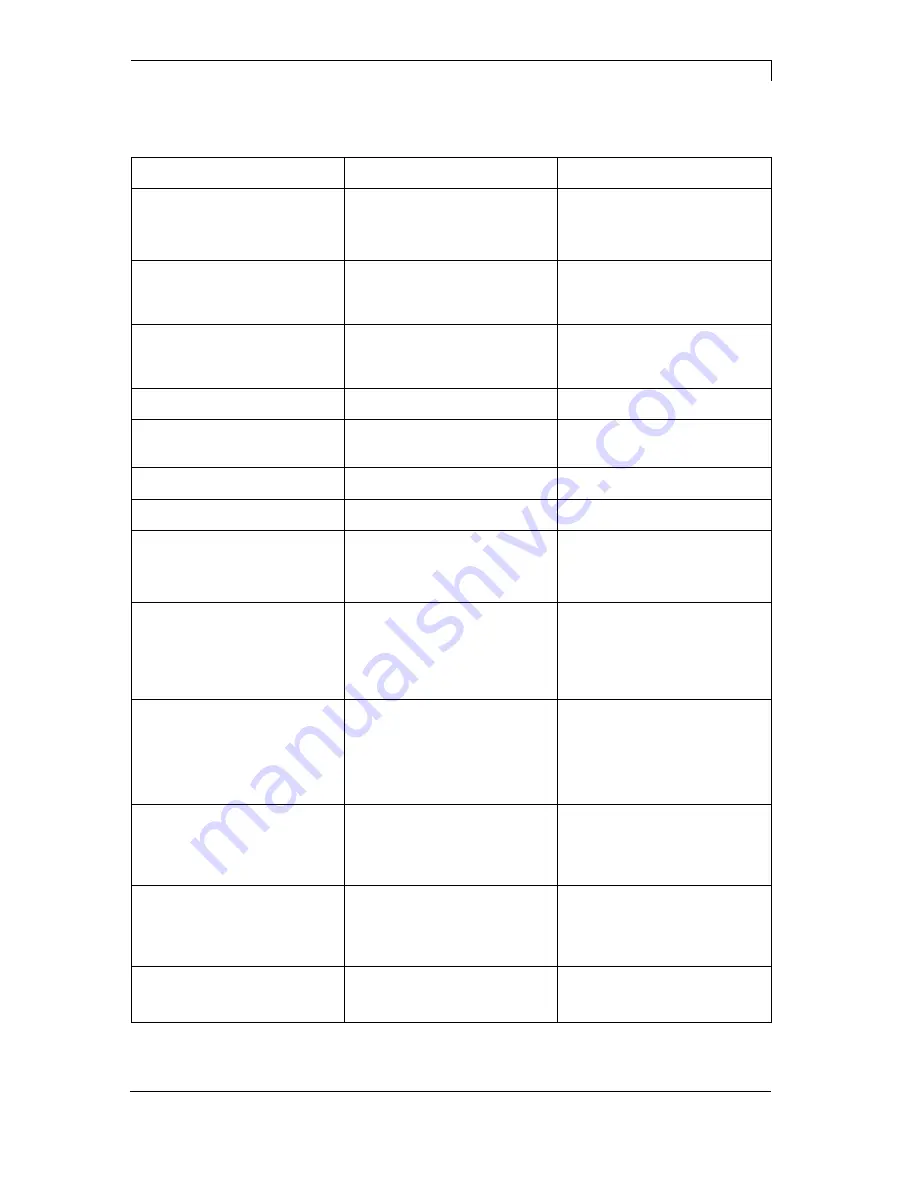
10 Error correction
Error message
Cause
Remedy
1
Line too high
Line rises up completely or
partly over the upper edge of
label.
Move line down (increase Y
value).
Check rotation and font.
2
Line too low
Line rises up completely or
partly over the bottom edge of
label.
Move line up (reduce X value).
Check rotation and font.
3
Character set
One res. several characters of
the text is res. are not available
in the selected font.
Change text.
Change font.
4
Unknown code type
Selected code is not available.
Check code type.
5
Unvalid position
Selected position is not
available.
Check position.
6
CV font
Selected font is not available.
Check font.
7
Vector font
Selected font is not available.
Check font.
8
Measuring label
While measuring no label was
found.
Set label length is too large.
Check label length and if labels
are inserted correctly.
Restart measuring anew.
9
No label found
No label available.
Soiled label photocell.
Labels not inserted correctly.
Insert new label roll.
Check if labels are inserted
correctly.
Clean the label photocell.
10
No ribbon
During the print order the
ribbon roll becomes empty
(front printhead).
Defect at the transfer ribbon
photocell (front photocell).
Change transfer ribbon.
Check transfer ribbon photocell
(service functions).
11
COM FRAMING
Stop bit error.
Check stop bits.
Check baud rate.
Check cable (printer and PC).
12
COM PARITY
Parity error.
Check parity.
Check baud rate.
Check cable (printer and PC).
13
COM OVERRUN
Loss of data at serial interface
(RS-232).
Check baud rate.
Check cable (printer and PC).