Curtiss-Wright | PG Drives Technology
SK77981-14
63 | R-net Technical Manual | Chapter 3 – Programming
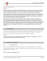
Axis Display
For parameter information - Refer to the Chapter – ISM8
Invert Channel Direction
For parameter information - Refer to the Chapter – ISM8
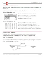
Channels
*Acceleration
For parameter information - Refer to the Chapter – ISM8
*Deceleration
For parameter information - Refer to the Chapter – ISM8
*Up Speed
For parameter information - Refer to the Chapter – ISM8
*Down Speed
For parameter information - Refer to the Chapter – ISM8
Up Current Limit
For parameter information - Refer to the Chapter – ISM8
Down Current Limit
For parameter information - Refer to the Chapter – ISM8
Endstop Autodetect
For parameter information - Refer to the Chapter – ISM8
Actuator Endstop Timeout
For parameter information - Refer to the Chapter – ISM8
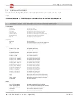
Intelligent Seating Module
Global
*Actuator Mode Entry Axis
Sets the default axis when Seating Mode is entered
Axis Setup
Axis Channels
Sets which actuator motor channels on the ISM will operate for a particular axis
Axis Display
Sets the user display for a particular axis
Invert Axis Direction
Sets whether a channel direction is inverted for a particular axis
Axis Name
Sets the text that will be displayed when an actuator is selected
Channels
*Acceleration
Sets the acceleration for each actuator channel
*Deceleration
Sets the deceleration for each actuator channel
*Up Speed
Sets the speed in the up direction for each actuator channel
*Down Speed
Sets the speed in the down direction for each actuator channel
Up Current Limit
Sets the maximum current output in the up direction for each actuator channel
Down Current Limit
Sets the maximum current output in the down direction for each actuator channel
Endstop Autodetect
Sets if the automatic endstop function for a particular actuator channel operates
Actuator Endstop Timeout
Sets the period of time before the drive is cut at an endstop position
Seating Module
Global
Actuator Mode Entry Axis
For parameter information - Refer to the Chapter – ELPM 90, JSM-LED & SM
Axis Setup
Axis Enabled
For parameter information - Refer to the Chapter – ELPM 90, JSM-LED & SM
Up Speed
For parameter information - Refer to the Chapter – ELPM 90, JSM-LED & SM
Down Speed
For parameter information - Refer to the Chapter – ELPM 90, JSM-LED & SM
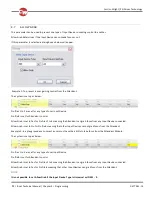
Axis End force
Actuator Endstop Timeout
For parameter information - Refer to the Chapter – ELPM 90, JSM-LED & SM
Axis Display
For parameter information - Refer to the Chapter – ELPM 90, JSM-LED & SM
Axes Inhibits
Up Assign
For parameter information - Refer to the Chapter – ELPM 90, JSM-LED & SM
Up: Inhibit in bands
For parameter information - Refer to the Chapter – ELPM 90, JSM-LED & SM
Down Assign
For parameter information - Refer to the Chapter – ELPM 90, JSM-LED & SM
Down: Assign in bands
For parameter information - Refer to the Chapter – ELPM 90, JSM-LED & SM
Battery
Low Battery Alarm
Sets whether there will be an audible alarm to signal a low battery condition
Low Battery Flash Level
Sets the point at which the battery gauge on the LCD screen starts to flash
Cable Resistance
Calibrates the system to compensate for the electrical resistance of the battery cables
Calibration Factor
Allows further fine calibration of the battery gauge
Low Voltage Cut-out
Sets the voltage level at which the low voltage timer will start
Low Voltage Time
Sets the period of time that the voltage must be below the above parameter before drive is cut
General
Brake Disconnected Alarm
Sets whether there is an audible alarm when a brake(s) is disconnected
Brake Fault Detect
Sets whether the Power Module will detect electrical faults in the wheelchair’s brakes
Brake Voltage
Sets the voltage output from the Power Module to the wheelchair’s electrical brakes
Soft Stop Rate
Sets the deceleration rate that is used while the wheelchair is “soft-stopping”


