INSTRUCTION MANUAL Digital Light Engraver
4
Machine description
Effective date
30.09.2013
4.1
Machine housing
•
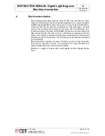
Linear guide elements (01), which are mounted on both the upper and
lower edges of the machine housing, run across the complete width of
the machine housing.
•
The vertically-mounted bridge (02) - where the head unit is located under
a protective cover - moves along the two linear guiding elements (01).
•
The screen frame (04), which is to be imaged, is held in place by two hor-
izontally placed U-channels (03).
•
The upper U-channel (05) can be vertically adjusted to accommodate dif-
ferent sizes of screen frames (04).
•
The screen frames (04) can be secured in both of the U-channels (03) by
means of pneumatically operated clamps.
CST GmbH
Königsberger Straße 117
47809 Krefeld - Germany
Page 25 of 69
Betriebsanleitung DLE-AF 01.0 engl.docx


