background image

 Glossary

3

DTE

data terminal equipment – any piece of equipment at which a communications 
path begins or ends

DVB

digital video broadcast

E

b

/N

0

energy-per-bit with respect to noise—also known as signal-to-noise level; when 
displayed on the remote terminal, E

b

/N

0

 is displayed as “Eb/No”

ECU

external control unit

ER

error – typically followed by a number to signify a specific error message

Eutelsat

intergovernmental organization that provides and operates a space segment for 
European telecommunications services

FEC

forward error correction

FIFO

first-in-first-out

Framing Unit

ComStream option card that provides all international overhead functions

FRU

field replaceable unit – a modular circuit card containing a microcontroller that 
communicates with another on the M&C card; also referred to as an option card or 
option module

Gaussian noise

White noise uniform across the entire range of frequencies that is introduced into 
a transmission channel from the environment; may interfere with a carrier signal. 
Also referred to as background electrical noise. May be abbreviated as WGN 
(white Gaussian noise).

GHz

gigahertz (10

1

)

GND

ground

HDLC

high-level data link control

hot-swap

process of installing or swapping certain option cards while the CM601 is 
powered up; only option cards containing the label Hot Plug/Pull on their filler 
plate can be swapped in this manner

HPA

high-power amplifier

Hz

hertz

I&Q channels

in-phase and quadrature-phase channels

Summary of Contents for CM601

Page 1: ...6350 Sequence Drive San Diego California 92121 2724 619 458 1800 888 559 0831 01 0779 401 Rev A 08 98 COMSTREAM A Spar Company CM601 PSK Digital Satellite Modem Installation and Operation Guide...

Page 2: ...escribed herein without notice 1998 ComStream Corporation All rights reserved ComStream is a registered trademark of ComStream Corporation Other brand and product names mentioned herein may be tradema...

Page 3: ...nt 3 1995 Amendment 4 11 1997 Listed under T V Product Service Certification System 13184 Council Directive 89 336 EEC 92 31 EEC and 93 68 EEC on the approximation of the laws of the Member States rel...

Page 4: ...iv Notice COMSTREAM A Spar Company...

Page 5: ...peration CM601 Architecture Overview 2 1 Chassis 2 1 Power Supply 2 3 Backplane 2 3 Standard Cards 2 3 Option Cards 2 4 System Monitor and Control 2 4 Modem Card 2 5 Modulator 2 5 Demodulator 2 6 Data...

Page 6: ...quirements 4 7 Test Procedure 4 7 Additional Testing 4 9 Completion of the Bench Top Test 4 9 Step 5 Install and Connect the CM601 in a Permanent Location 4 10 Step 6 Configure the CM601 4 11 Acquire...

Page 7: ...erform an IF Loopback 7 7 Intermediate Data Rate IDR Compatible Operation 7 8 Perform an IF Loopback 7 9 Chapter 8 Fault Handling Troubleshooting and Maintenance Fault Handling 8 1 Fault Reporting 8 2...

Page 8: ...20 Card Removal Procedure 8 20 Maintenance 8 21 Appendix A Technical Specifications System A 1 Low Speed Modem A 3 BERT Optional A 4 Regulatory Compliance A 5 Available Option Cards A 5 Appendix B Int...

Page 9: ...ltablauf C 2 Sicheren Stellplatz einr umen C 2 N e und Feuchtigkeit vermeiden C 2 Hitze Feuchtigkeit und Staub ist zu vermeiden C 2 F r ausreichende Ventilation sorgen C 2 Richtiger Netzanschlu C 3 St...

Page 10: ...6 Figure 2 6 M C Card 2 7 Figure 3 1 Clock and Data Signal Timing Diagram 3 5 Figure 3 2 Relay Sense Pins 3 11 Figure 4 1 CM601 Rear Panel 4 6 Figure 6 1 CM601 Front Panel 6 1 Figure 6 2 CM601 Front...

Page 11: ...Relay Sense Pins 3 12 Table 4 1 Straight Through Cable Pinout Specifications 4 7 Table 4 2 Power Up Sequence 4 8 Table 4 3 Front Panel Button Operation Verification 4 9 Table 4 4 Commonly Used Acquisi...

Page 12: ...xii Contents COMSTREAM A Spar Company...

Page 13: ...e which covers the following content area System configuration issues to help you better plan your system design installation and operation in order to avoid potential system issues CM601 commands con...

Page 14: ...mization Figures depicting equipment may differ from those at your site therefore refer to the labeling on your ComStream equipment to identify the components An effort has been made to use illustrati...

Page 15: ...uthorization number will not be accepted 4 ComStream shall not accept any responsibility for returned products that are improperly packaged and or damaged in shipment If possible please use original s...

Page 16: ...mstances that may have led to the problem This information is essential for ComStream repair technicians to reproduce diagnose and correct the problem Upgrade or modification include a complete descri...

Page 17: ...you need to operate the CM601 However in the event that you need further assistance or if problems are encountered ComStream has set up a Customer Support Line for your use Please feel free to contac...

Page 18: ...heating and ensure that the ventilation slots are not blocked place the CM601 on a smooth hard surface that has at least two inches of clearance around the unit and adequate air circulation If the CM6...

Page 19: ...ller ground the system to protect against voltage surges and built up static charges It is recommended to install system primary and secondary lightning surge protective devices for CM601 units having...

Page 20: ...r satellite communication equipment with the CM601 Clean the CM601 Before cleaning the CM601 unplug it from the wall outlet Do not use any type of abrasive pads scouring powders aerosol cleaners or so...

Page 21: ...is at the rear panel much like the circuit cards in a PC The power supply module and front panel are also removable and replaceable in the field This modularity simplifies sparing as only individual o...

Page 22: ...ed Solomon codec satellite control channel SCC and the CX101 801 line of redundancy switches are fully compatible with the CM601 modem Applications The CM601 is particularly well suited for bandwidth...

Page 23: ...ed ASCII protocol and RS 232 electrical levels In addition through the use of a remote command the front panel can be disabled to prevent tampering by unauthorized personnel if required Applications r...

Page 24: ...thms to verify proper operation An optional bit error rate tester BERT that allows satellite link integrity testing through the remote terminal or front panel which helps reduce satellite circuit oper...

Page 25: ...1 Figure 2 1 CM601 Front Panel The front panel consists of A 2 line 24 character LCD which displays the modem ID on the first line and on the second line commands used to configure monitor and control...

Page 26: ...slot numbers 1 5 and 4 correspond to the slot numbers used in the CM701 DT7000 and DT8000 earth stations These slot numbers or identifiers are used for reference while cabling a CM601 or when setting...

Page 27: ...andshake signals between cards The backplane hardware supports three elementary clock and data transmit paths and three elementary clock and data receive paths Each of the transmit and receive paths c...

Page 28: ...different than that on the receive side For example the required transmit data rate may be 512 kbps with an RS 449 electrical interface However the required receive data rate may be 9 6 kbps with an R...

Page 29: ...1 Transmit Process 4 Provides the data to the modulator modem card for processing the data processing consists of a Scrambling ComStream version V 35 or IDR b Differential encoding c Convolutional enc...

Page 30: ...baseband signals are digitized After the signals are digitized all remaining signal processing is digital 5 The first digital block encountered after the analog to digital converters is a digital bas...

Page 31: ...vailable using the option card slot Doppler Buffer ComStream s Doppler Buffer is a feature that is standard on every CM601 modem card It buffers data received from the satellite on a first in first ou...

Page 32: ...nce to the entire CM601 chassis and all cards within it A high stability oven controlled crystal oscillator OCXO is available as an option The benefits of this single frequency reference are as follow...

Page 33: ...each option card Low Speed Modem Card Connectors The three connectors listed in Table 3 1 are found on the CM601 Low Speed modem card Tx Rx Connector The Tx Rx data connectors provide the data clock...

Page 34: ...nned out as data communications equipment DCE therefore the user data equipment must be configured as data terminal equipment DTE in order to make a straight cable between them Table 3 2 Electrical Sp...

Page 35: ...n 15 No connection N C Open 16 No connection N C Open 17 Transmit timing TT A Input 18 Reserved1 Reserved 19 Signal ground SG Ground 20 Common Ground 21 Reserved1 Reserved 22 Send data SD B Input 23 S...

Page 36: ...connection N C Open 10 Send timing ST A Output 11 Receive timing RT A Output 12 Transmit timing TT A Input 13 Reserved1 Reserved 14 Send data SD A Input 15 Receive data RD A Output 16 No connection N...

Page 37: ...t clock generated by the CM601 when configured for Internal timing This clock is accurate to better than 4 ppm Transmit Timing TT The transmit clock provided to the CM601 by the DTE Typically the CM60...

Page 38: ...l signals are single ended RS 232 level signals following standard RS 232 conventions Applications Not Requiring Data Control Signaling For most CM601 applications data control signaling is not requir...

Page 39: ...command or the remote TP command For normal CM601 operation the output power of the modulator is set between 5 to 25 dBm in 0 1 dB steps The output frequency is programmable in the range of 52 to 88M...

Page 40: ...the BR MDP MEI MPT and MPA commands RS 232 Applications A 9 to 25 pin cable is included in every CM601 shipping kit for use with RS 232 applications This cable is used to convert the 9 pin remote inte...

Page 41: ...2 Receive Data Output 3 Transmit Data Input 4 Not connected Open 5 Signal Ground Ground 6 Data Set Ready Output 7 Request to Send Input 8 Clear to Send Output 9 Not connected Open Table 3 10 RS 232 R...

Page 42: ...r remote terminal The status relay connector pinout is provided in Table 3 12 Table 3 11 RS 485 Remote Connector Pinout for DCE Pin Signal Name Direction 1 Signal Ground Ground 3 Transmit Input 5 Rece...

Page 43: ...condition when power is off This condition is indicated by contact between C and B with no contact between C and A The maximum power that can be passed through the relay contacts is 1 VA Relay Sense...

Page 44: ...s some equipment status relays are open while others are closed The Fault Relay Sense External Signal Polarity FRX command is used to define the fault polarity of the relay sense pins as open or close...

Page 45: ...separate quick reference card that accompanies this guide This quick reference is for those Familiar with satellite communications Experienced with ComStream products and the CM601 Installation Proce...

Page 46: ...this system configuration and that should be considered include Acquisition performance Error correction coding Modulation types Modem performance Data throughput requirements Link availability requi...

Page 47: ...will save time and provide ease of installation by identifying decisions about configuration that should be made beforehand Installation Data Sheet General Information Date __________________________...

Page 48: ...which includes Modulator bit timing MB Modulator latching clock ML Once all the above parameters have been defined continue with step 2 Step 2 Inspect the CM601 System Before performing a bench top t...

Page 49: ...isually inspect the system to ensure that no physical damage has occurred during shipping 3 Verify that the CM601 configuration matches the features and options that were ordered 4 If any discrepancie...

Page 50: ...ned onto the metal These labels include the card name and reference designator for each connector Issuing Commands In order to enter the necessary commands to complete both the bench top test and init...

Page 51: ...QuickLink RS 232 serial port AC power access Test Procedure When following the bench top test procedure note that the exact location of the connector J numbers may vary from one CM601 to another depe...

Page 52: ...time while all LED lamps are tested CM601 information appears for example ComStream CM601 ID message Unit serial number Pass or fail indication for the power up self test sequence Power Up Test Messa...

Page 53: ...e and extensive specification compliance is necessary Specification compliance tests for RF power dynamic range acquisition range acquisition time symbol rate range aggregate power and many other para...

Page 54: ...her solid connection to earth ground with heavy gauge wire c Connect the IF coaxial cables to the modem card s TxIF and RxIF connectors d If remote operation is desired connect the RS 232 plug of an a...

Page 55: ...the CM601 The CM601 can accommodate a variety of configurations to allow for customization of your network communications system To configure the CM601 1 Use the front panel or remote terminal to conf...

Page 56: ...ient for operation Modem has searched the entire acquisition range check the AR parameter Signal is present on the RxIF connector Receive carrier is at the expected frequency AG parameter is at an acc...

Page 57: ...k cable Satellite loopback Validates the coaxial cabling between the CM601 and the RF equipment confirms the radio transmit and receive paths and the satellite receive and transmit paths Far data loop...

Page 58: ...parameters and configuration parameters but not change parameters this mode is indicated by a yellow ViewOnly message on the front panel to the right of the LCD display and above the Enter button Lock...

Page 59: ...supported by the CM601 are ASCII and ComStream packet protocol ASCII protocol is provided for use with character based computer terminals These terminals issue an asynchronous ASCII character to the C...

Page 60: ...f command parameters use the syntax DP For redundant configurations a slot number must precede the command slot number command mnemonic parameter Direct slot addressing of commands is not required for...

Page 61: ...nds have parameters that can be modified and entered to change the operating characteristics of the CM601 and direct it to perform real time functions Monitor These commands provide query view only in...

Page 62: ...acquisition search will begin frequency is expressed in hertz AQ Acquisition Config NV 0 disable 1 enable 2 fast 1 Determines acquisition status of the demodulator or to restart acquisition AR Acquisi...

Page 63: ...ate of the remote device BRE Bert Reset And Control BConfig V 0 stop 1 start 2 reset 2 Stops starts or resets the BERT BSF Bert Sync Fault History BMonitor Determines if the BERT has stayed in synchro...

Page 64: ...t reset value in NV memory DB Doppler Buffer Fill Level Monitor Displays the number of data bits currently in the data buffer DBB Doppler Buffer Size Config NV 64 to 8192 8192 Sets the size of the dat...

Page 65: ...tion and operating parameters DP command is not supported by ComStream packet protocol EB Eb N0 Level Monitor Displays current Eb N0 level response values 0 1 dB steps from 0 to 21 dB if issued when t...

Page 66: ...to ensure proper operation after installation LB Loopback Mode Config V 0 disable 2 near data 4 far data 0 Tests and troubleshoots system connections LBT LCD Backlight Timeout Config NV 0 always off...

Page 67: ...Data Time Config V absolute 00 00 00 to 23 59 59 seconds 0 to 172800 Sets the time or time delay for executing the commands buffered in the MD commands time value can be entered in absolute time or in...

Page 68: ...D command represents the data rate that is output from the active I O card on the receive side of the CM601 PRP Primary Receive Path Config NV Consists of entry slot data slots and exit slot for data...

Page 69: ...ompatible 2 IDR IESS 308 compatible 1 Establishes descrambling algorithm applied to receive data stream SHP Show Paths Monitor Displays current backplane connections SM Scrambling For Modulator Config...

Page 70: ...rd 1 corresponds to slot 1 1 if data I O card in slot 1 Selects active transmit I O card by slot number for CM601 configurations with multiple data interface cards installed TM Transmit Modulation Typ...

Page 71: ...of entry slot data slots and exit slot for data path Sets ternary transmit data path VBM Verbose Mode Config NV 0 disabled 1 enabled 0 Displays returned ER messages with brief description when enable...

Page 72: ...attempting a loopback test when no modulator has been installed Check hardware configuration and settings and make modifications if required Reenter the command using the correct syntax ER 4 Command...

Page 73: ...ters navigating through the command tree as well as command syntax and entry For information on fault monitoring logging and conditions refer to the chapter on fault handling For a detailed descriptio...

Page 74: ...command and current value of the parameter are displayed in the format command parameter If the command is specific to a card in a duplicate card configuration the slot number will precede the comman...

Page 75: ...Rx Sync message appears white if the CM601 is not synchronized to the receive signal This status message is not directly affected by any push buttons on the front panel Fault Red Not visible Illumina...

Page 76: ...w the 24 character LCD are three buttons that have T shaped icons above them They are used for selecting commands from the command tree Modify up and down Used to scroll up and down through parameter...

Page 77: ...iff Encoding Rx Diff Decoding Tx Filter Type Rx Filter Type Acquisition Tx Pwr Level Tx Pure Carrier Modem Loopback Buffer Mode Buffer Delay Buffer Buffer Clk Sel Tx Clock Source Tx Scrambling Rx Scra...

Page 78: ...C Access to monitor and control functions Remote commands associated with the remote control interface port S W Ver access to software version number of each installed card in the CM601 Misc miscellan...

Page 79: ...h the command list use one of the following methods Press the left or center LCD button Each button press will scroll down one command in the command list When the bottom of the list is reached pressi...

Page 80: ...the Previous button to return to BConfig BMonitor 5 Select BConfig 6 Scroll to the BERT Error command 7 Select Insert and press the Enter button 8 Press the Previous button three times to return to C...

Page 81: ...ue of the parameter will increase by one hundred and appear as 5057 4 Issue the command by pressing the Enter button An asterisk will appear briefly to the left of the command parameter and then disap...

Page 82: ...n comma 0 through 9 A through Z c Repeat steps a and b until the entire command appears as desired 4 Issue the command by pressing the Enter button If the command was a query the LCD will display the...

Page 83: ...n SWV SWV NV Display of software version by slot n 1 2 3 4 5 6 7 CONFIG M C MISC AA Terminal emulator allows commands to be issued and modified from the front panel using use remote command syntax Lam...

Page 84: ...uffer Delay DBD NV Doppler buffer delay in msec 1 to 1000 Buffer DBR V Doppler buffer reset RESET Buffer Clk Sel DCS NV Doppler clock select Ext TT user supplied transmit Ext Conn user supplied extern...

Page 85: ...Chan Err Rate CE Channel error rate query nnn Hz Tx Clk TT Transmit clock frequency query n nnn kHz Buffer Fill Level DFL Doppler buffer fill level query response 1 empty to 99 full Rx Clk RTF Receiv...

Page 86: ...6 14 Front Panel Operation COMSTREAM A Spar Company...

Page 87: ...are used in the examples ComStream closed network compatible operation with a standard CM601 card set ComStream closed network compatible operation with a CM601 configuration consisting of two data in...

Page 88: ...he IF frequencies used in this example are representative only You must calculate the actual IF frequencies based on the RF equipment used and the frequencies assigned by the satellite provider prior...

Page 89: ...000 bps enter PTD 64000 13 Check the transmit symbol rate by issuing a transmit symbol rate query command TR which should return a value of 64000 sps 14 Select a user receive data rate of 64000 bps en...

Page 90: ...provider prior to any actual RF transmissions To configure the system 1 Ensure that the Test Mode LED on the front panel is not illuminated If it is illuminated perform the following steps a Turn all...

Page 91: ...r TC 1 11 Select Sequential rate 1 2 for decoding enter RC 1 12 Select a user transmit data rate of 9600 bps enter PTD 9600 13 Check the transmit symbol rate by issuing a transmit symbol rate query co...

Page 92: ...off enter LB 0 b Turn pure carrier mode off enter PC 0 c Turn the internal BERT off enter BEN 0 2 Configure the modem for the timing mode noted in the assumptions select DTE to provide transmit timing...

Page 93: ...ch should return a value of 273067 sps Perform an IF Loopback To perform an IF loopback connect an IF cable between the Tx IF and Rx IF connectors The modem should acquire almost immediately If it doe...

Page 94: ...re carrier mode off enter PC 0 Turn internal BERT off enter BEN 0 2 Configure the modem for the timing mode noted in the assumptions Select the DTE or external Framing Unit to provide transmit timing...

Page 95: ...ould return a value of 1640000 sps Perform an IF Loopback To perform an IF loopback connect an IF cable between the Tx IF and Rx IF connectors The modem should acquire almost immediately If it does no...

Page 96: ...7 10 Configuration Examples COMSTREAM A Spar Company...

Page 97: ...ng general CM601 maintenance Fault Handling The CM601 continually checks for internal hardware faults that may require card replacement and for operational or fault conditions that may require a chang...

Page 98: ...re power switch turned off and unplugged unit faults Fault Relay Sense External Signal Polarity FRX specifies how the CM601 will interpret the external faults that are monitored by the relay sense pin...

Page 99: ...10 faults in the fault history log are recorded with a date and time stamp and are saved in volatile memory for subsequent viewing Fault Queries The status of the CM601 can be quickly determined by ch...

Page 100: ...fault log register was cleared The list includes fault descriptions with date and time stamps The information is saved in volatile memory for subsequent viewing This feature is very helpful when track...

Page 101: ...4 8 Tx Bit Timing Fault H or O Modulator bit time synthesizer is not locked Valid only when the CM601 is operating in external or loop timing mode Type H When this fault occurs the modulator IF trans...

Page 102: ...time clock that is within about 300 ppm of the clock rate for which it is configured 13 4096 NVRAM Failure H A parameter stored in a NV memory location is corrupt Repeated occurrence of this fault in...

Page 103: ...specific message Review the option card fault messages 29 268435456 Tx FIFO Full Fault O Data buffer on the modulator has overflowed or underflowed Occurs briefly when changing modulator data rates or...

Page 104: ...nge fault Bit 7 Carr track sync loss Bit 10 Rx carr range fault Bit 13 NVRAM failure Fault Overlay Masks CM601 overlay mask commands can be used to designate the fault conditions that trigger the fron...

Page 105: ...e overlay mask bits for all nonselected faults is set to 0 Both the current fault status register and the status relay are real time indicators If a fault condition exists it will be indicated If no f...

Page 106: ...rface Parity and baud rate parameters are not properly configured Ensure that the selected parity 8 none or 7 odd and baud rate match that of the terminal Transmit Problems Carrier is not being transm...

Page 107: ...ectral inversion problem introduced in the upconversion or downconversion process Use the MI or DI command to compensate Spectral inversion problems should be corrected on the uplink modulator Signal...

Page 108: ...able a power meter spectrum analyzer or frequency counter to the TxOut connector on the rear panel 2 Enable the modulator by issuing either a remote EM 1 command or pressing the Tx Enable button on th...

Page 109: ...loopback Satellite loopback Far data loopback Long term BER measurement Near Data Loopback Test A near data loopback test shown in Figure 8 1 validates the connection between the DTE and the CM601 Fig...

Page 110: ...atch the transmit parameters 4 Enable the modulator by either issuing a remote LB 1 command or the front panel Loopback IF command If error free data is not received by the DTE verify Installation of...

Page 111: ...nsmit parameters are set correctly and that all loopbacks are disabled 4 Enable the modulator by issuing EM 1 A successful satellite loopback test is performed when the DTE transmits and receives its...

Page 112: ...nk analysis performed prior to installation Typical levels range from 6 to 10 dB The CM601 BERT if available can be used to validate a far data loopback instead of a DTE data analyzer if necessary Lon...

Page 113: ...BIT command Individual Board Level Hardware Test To perform a board level hardware test on an individual card from a remote terminal or using the front panel terminal emulator perform the following st...

Page 114: ...storing these devices 4 Carefully remove the EPROM or PLCC from the board using an IC pulling device 5 Store the removed EPROM or PLCC until the new one is installed and verified 6 Carefully align and...

Page 115: ...onsist of the following An extractor which is used to remove the card from the chassis A filler plate which must be screwed into the chassis once the card is installed This ensures adequate grounding...

Page 116: ...pecific requirements For information on the autoconfiguration command refer to the CM601 Reference guide All ComStream cards contain static sensitive electronics Use standard antistatic procedures whe...

Page 117: ...eed to perform is keeping the air intake grill free of debris blockage or excessive dust to ensure that the modem receives a free flow of air To clean the CM601 modem first remove power from the unit...

Page 118: ...8 22 Fault Handling Troubleshooting and Maintenance COMSTREAM A Spar Company...

Page 119: ...4 8 ksps to 512 ksps in 1 sps steps for higher speed options contact ComStream Customer Service Modulation types BPSK QPSK Code rates Sequential 1 2 3 4 and 1 uncoded Viterbi 1 2 3 4 7 8 and 1 uncoded...

Page 120: ...Viterbi rate 3 4 7 0 dB Eb N0 for 10 7 BER Viterbi rate 7 8 8 0 dB Eb N0 for 10 7 BER System performance Sequential rate assumes a long decoder length IDU performance decoder performance ODU performa...

Page 121: ...itter Standard Peak DS 1 CEPT 10 2 unit intervals per Bell Tech Pubs 41451 per G 832 Transmit Power Power Range Resolution Accuracy On Off isolation 5 0 to 25 0 dBm 0 1 dB steps 0 5 dB 60 dB Tx output...

Page 122: ...um BERT optional Patterns Fixed Pseudorandom All marks all spaces 1 1 8 bit user 511 29 1 Error analysis Number of bit errors Number of blocks with errors Average BER BER over previous block Average b...

Page 123: ...Susceptibility EN61000 4 2 ESD EN61000 4 3 Radiated Susceptibility EN61000 4 4 EFT EN61000 4 5 Surge EN61000 4 6 Conducted Immunity EN61000 4 8 Magnetic Field EN61000 4 11 Voltage Variation ENV50204 K...

Page 124: ...A 6 Technical Specifications COMSTREAM A Spar Company...

Page 125: ...m the remote terminal and front panel Listing of BERT commands Instructions for initiating a standard BER test and an explanation of its results Tips on advanced BERT operation and error analysis Func...

Page 126: ...t and counters which provide the BER block error rate etc The received data is passed uninterrupted to the external interface Issuing BERT Commands BERT commands can be issued and the results monitore...

Page 127: ...7 01 Config Monitor Faults 4 Systm 4 M C More 5 Modem More 1 RS449 1 BERT More BERT Test Mode BERT Control BERT Error BERT Pattern BERT Usr Ptr n BERT Blk Length BERT SyncLvl BERT Sync BERT Sync Histo...

Page 128: ...m the front panel refer to the steps for enabling the BERT however select the disable parameter in step 4 BERT Command Summary There are two types of BERT commands Configuration used to access modify...

Page 129: ...SET RESET BERT pattern type BPT NV 0 1 2 3 4 INSERT BERT reset and control BRE V 0 1 2 2 9 1 USER 1 1 MARK SPACE 2 15 1 2 9 1 BERT synchronization threshold BST NV 0 1 0 to 255 85 BERT transmit error...

Page 130: ...RT Test Mode ENABLE command The Test Mode LED illuminates If the modem is receiving data from another modem and from a BERT with the same pattern the BERT will synchronize and the monitor information...

Page 131: ...reset The BERT reset and control command can be used to temporarily freeze the display of all status parameters 3 Identify and troubleshoot BERT monitor parameters that are indicating faults or errors...

Page 132: ...hooting DCE equipment external to the modem To do this operate the modem with the BERT generating a repeating 8 bit pattern The resulting receive pattern can be used by a technician performing oscillo...

Page 133: ...ntifiziert die Information zur korrekten Bedienung Ihrer Anlage einschlie lich aufschlu reicher Tips Abk rzungen oder wichtige Erinnerungssignale Warn Ikon identifiziert Informationen und mu sofort un...

Page 134: ...digen Sie bitte sofort ComStream da die M glichkeit eines ernsthaften Schadens an dem CM601 und seiner Best ckung besteht Hitze Feuchtigkeit und Staub ist zu vermeiden Um interne Sch den zu vermeiden...

Page 135: ...Ende Dieses Kabel is HAR genehmigt bis zu 250 V AC bei 6A und stimmt mit den internationalen Farbvorschriften berein wo Erdung gr n gelb ist Null Leiter blau ist und der Anschlu braun Sollten diese Fa...

Page 136: ...egt werden damit sich keine Stolpergefahren bilden und die Kabel nicht eingeklemmt werden Besonderer Wert soll auf die Stecker und Steckerbuchsen gelegt werden wie z B Multi Steckvorrichtungen und an...

Page 137: ...n man den Strom nicht abschaltet und dies nicht beachtet wird kann man dadurch das Modem die Leiterplatten oder andere damit zusammenh ngende Best ckung besch digen Anti Statik Schutz Ein ausreichend...

Page 138: ...hen Spannungen und anderen Gefahren aus und machen dadurch Ihre Garantie nichtig Setzen Sie sich mit dem Kundendienst von ComStream in Verbindung um fachgerechten Kundendienst zu bekommen Die folgende...

Page 139: ...cific integrated circuit attenuation decrease in signal power absolutely or as a fraction of a reference value received signal is lower in volume than the transmitted signal due to losses in the trans...

Page 140: ...ComStream PSK Digital Satellite Modem codec coder decoder C O E ComStream customer order entry number CT carrier tracking lock CW continuous wave refers to transmission of an unmodulated carrier D A...

Page 141: ...onal overhead functions FRU field replaceable unit a modular circuit card containing a microcontroller that communicates with another on the M C card also referred to as an option card or option modul...

Page 142: ...al consortium established by a treaty between countries that own and operate an extensive system of satellites for international communications services interactive two way communications I O input ou...

Page 143: ...fers to the CM601 M C card that is the interface between the user and any other modules in the CM601 Mbps million bits per second MCPC multiple channels per carrier MHz megahertz mod modulator ms or m...

Page 144: ...ther QPSK quadrature phase shift keying Quaternary or quadrature phase shift keying in which four discrete phases of the carrier are used In QPSK modulation four phases of the RF carrier each differin...

Page 145: ...signed to use the 70 MHz image and the receive RF does not similarly invert the signal that is undo the inversion then there is a spectral inversion and the signal cannot be recognized by the receiver...

Page 146: ...illator Viterbi a standard form of FEC decoding the other standard form is Sequential volatile volatile memory command parameters that direct the CM601 to perform a real time function or enter a test...

Page 147: ...2 3 rear panel 4 6 specifications A 1 theory of operation 2 1 commands BERT summary B 4 front panel 6 1 functional types 5 2 issuing 4 6 5 2 memory types 5 2 remote 5 1 security 5 13 summary 5 2 summ...

Page 148: ...ications 3 8 RS 449 clock data relationship 3 5 electrical specifications 3 2 external connections 3 1 pinout 3 3 RS 485 applications 3 10 remote connector pinout 3 10 RxIF connector 3 7 S security co...

Page 149: ...CM701 CM601A Standard Speed and Low Speed Modem Card 6340 Sequence Drive San Diego California 92121 858 458 1800 01 0799 401D 08 02...

Page 150: ...liability arising out of the application or use of any products component parts circuits software or firmware described herein ComStream further does not convey any license under its patent trademark...

Page 151: ...Module 2 Modulator and Demodulator 2 Doppler Buffer 3 Compatibility 3 Option Card Installation Configuration and Removal CM701 Chassis Slots 5 Modem Card Components 6 Installation Procedure 6 Configur...

Page 152: ...5 IF Loopback 46 Far Data Loopback 46 Appendix A Technical Specifications and Pinouts System Specifications 49 Modulator Specifications 50 Demodulator Specifications 51 Mechanical and Environmental Sp...

Page 153: ...ard Operation 2 Figure 2 1 Standard CM701 Configuration with Modem Card Installed 5 Figure 2 2 Modem Card 6 Figure 3 1 CM701 CM601A Modem Front Panel Command Tree 17 Figure 5 1 Near Data Loopback 45 F...

Page 154: ...3 Remote Command Summary Listing 27 Table 3 4 Front Panel Command Summary Listing 33 Table 4 1 Standard and Low Speed Modem Card Operational Faults 57 Table A 1 Connector DB 25 female 66 Table A 2 Ad...

Page 155: ...the following icons designed to help you identify important information The note icon identifies information for the proper operation of your equipment including helpful hints shortcuts or important...

Page 156: ...reight collect or without a return material authorization RMA number will NOT be accepted 4 Radyne ComStream shall not accept any responsibility for returned products that are improperly packaged and...

Page 157: ...gnose and correct the problem Upgrade or modification please include a complete description of the current configuration and the desired change s This information will allow a customer service represe...

Page 158: ...lower vases coffee cups rain from open windows and so on If the Modem card is exposed to any liquid contact Radyne ComStream as serious damage could occur to the Modem card or its components Avoid Hea...

Page 159: ...elf as there are no user serviceable parts Opening or removing components may expose you to dangerous voltages or other hazards as well as void your warranty Contact Radyne ComStream Customer Service...

Page 160: ...xii Safety Precautions 01 0799 401D 08 02...

Page 161: ...th the following features On board modulator and demodulator with programmable data rates from 9 6 kbps to 4 375 Mbps on the Standard Modem card and 9 6 kbps to 512 kbps on the Low Speed Modem card On...

Page 162: ...be configured The CM601A chassis has one slot for one additional interface card to which the Modem card will default for I O if the on board I O port is disabled Modulator and Demodulator CM701 CM601A...

Page 163: ...ing the satellite receive clock signal The received data is then output from the Doppler Buffer by selecting either the transmit receive external or internal clock The size of the buffer is user confi...

Page 164: ...4 Functional Description 01 0799 401D 08 02...

Page 165: ...three horizontal card slots Figure 2 1 The Modem card is shown installed in slot 5 Figure 2 1 Standard CM701 Configuration with Modem Card Installed Slots 1 2 and 3 are vertical slots for option cards...

Page 166: ...AUTION All Radyne ComStream cards contain static sensitive electronics Use standard antistatic procedures when handling the cards For full Modem card functionality Monitor and Control M C firmware ver...

Page 167: ...r Buffer 1 Issue the appropriate command to set the clock that will be used to clock the data out of the Doppler Buffer External transmit timing remote command DCS 1 front panel command BufferClkSel E...

Page 168: ...nds chapter for more information about these commands If you are using multiple interface cards up to three on the CM701 you must disable the on board I O with MIO 3 then configure the interface cards...

Page 169: ...d Operation Guide Card Removal Procedure To remove a Modem card from the chassis 1 Check the Modem card filler plate as follows a If the words HOT PLUG PULL are present and M C firmware is version 5 5...

Page 170: ...10 Card Removal Procedure 01 0799 401D 08 02...

Page 171: ...command is typed with the appropriate parameter and then Enter is pressed Table 3 1 Command Memory Types Memory Type Description Nonvolatile NV Command parameters stored in NV memory do not have to b...

Page 172: ...ing Remote commands are summarized in alphabetical order in Table 3 3 For each command the following information is provided in the table Command mnemonic and command name Function and memory type Fun...

Page 173: ...1 1 0 AO value not stored in NVRAM 1 Stores AO value in NVRAM default AQ Acquisition Status Config NV Acquisition 0 1 2 1 0 STOP 1 NORMAL 2 FAST acquisition use the ABB command for faster acquisition...

Page 174: ...Select Config V Ext Bit Clk 0 1 2 3 1 Hi stability M C only 0 not through M C 1 SMA to TTL terminated 2 SMA to TTL unterminated 3 15 pin D status relay MFB Modem Fault Bypass Config NV Mdm Flt Bypass...

Page 175: ...enable RE REset modem Config V Modem Reset Reset the modem to default settings RM Rx Modulation type Config NV Rx Mod Type 0 1 1 0 BPSK 1 QPSK RO Rx Offset frequency Config NV Rx Offset Queries receiv...

Page 176: ...ype 0 1 1 0 BPSK 1 QPSK TP Transmit Power Config NV TxPwrLevel 50 to 250 150 Transmit output power 50 represents 5 0 dBm TR Transmit Symbol Rate Config NV TxSymRate 4800 to 2500000 1544000 Transmit sy...

Page 177: ...e 7 Modem More Modem Reset LoopBack Init Factory Default Initialize New Firmware Tx Active IO Rx Active IO Remote S W Ver Misc Baud Rate Remote Control Remote Dat Par Protocol Packet Address 1 card so...

Page 178: ...er buffer delay in milliseconds Buffer Fill Level DFL 0 to 99 Displays Doppler buffer fill level as percentage full from 0 empty to 99 full Buffer Mode DBM Buffer Bypass Doppler buffer mode BufferClkS...

Page 179: ...z Tx Clock Source MB EXT INT LOOP Transmit timing Tx Code Rate TC Uncoded Seq 1 2 Seq 3 4 Vit 1 2 Vit 3 4 Vit 7 8 Set transmit FEC encoder type and rate Tx Diff Encoding DM OFF remote equivalent 0 ON...

Page 180: ...issue the remote command ABB 5 AE Automatic Modulator Enable Config NV Use this command to automatically enable or disable the modulator TxIF at modem power up or reset or upon resolution of a modula...

Page 181: ...Offset Frequency Config NV Use this command to set the offset frequency from which the acquisition search will begin The acquisition offset frequency is expressed in Hz AO freq freq parameter values...

Page 182: ...More Modem Acquisition AR Acquisition Range Config NV Use this command to define the size of the frequency range over which the demodulator will search for the carrier The acquisition range is express...

Page 183: ...led If CE is issued when the CM701 is not locked to a receive carrier or if the CM701 is operating uncoded a remote ER 4 error response or N A front panel message will appear CE The returned two digit...

Page 184: ...ength is not a valid buffer size the setting will be automatically rounded up to the next valid buffer size 2 Issue the DBD command to review the resulting buffer length The time displayed is the actu...

Page 185: ...differential decoding on the demodulator DD decoding type Remote front panel decoding type parameter values and their front panel setting equivalents are 0 OFF disables differential decoding 1 defaul...

Page 186: ...l Encoding on Modulator Config NV Use this command to control differential encoding on the modulator DM encoding type Remote front panel parameter values are 0 OFF disables differential encoding 1 def...

Page 187: ...eive clock and data signals RT and RD to drive the modulator in place of the transmit clock and send data signals TT and SD from the DTE From the front panel select Config 4 Systm LoopBack MB Modulato...

Page 188: ...is only available when using the high stability M C card MCS interface type interface type parameter values are 0 OFF default external bit timing clock is not routed through the M C card and onto the...

Page 189: ...OD reports only modulator and option card faults From the front panel select Config More Modem Mdm Flt Bypass device MIC Modem I O Control Config NV Use this command to set how the on board I O type w...

Page 190: ...al loopback modes MLB mode mode parameter values are 0 DISABLE default normal card operation loopback mode is disabled 1 IF modulator output is routed to the demodulator input The demodulator paramete...

Page 191: ...cations 2 SMS filter for Intelsat and Eutelsat compatible open network applications From the front panel select Config More Modem Tx Filter Type MST Internal Clock Frequency Monitor Use this command t...

Page 192: ...mission The pure carrier signal is used for diagnostic and system installation When enabled the ST clock on the data I O connector is reduced to 0 Hz From the front panel select Config More Modem Tx P...

Page 193: ...l select UserTxData PTD is a one way macro command issuing PTD is effective only if no data rate or symbol rate related commands have been issued to individual cards since the PTD value was entered Is...

Page 194: ...onds to 9 6 kbps to 512 kbps The default is 512000 From the front panel select Config More Modem RxDataRate RDI Receive Data Invert Config NV Use this command to specify whether the data received from...

Page 195: ...er frequency RO The response is displayed in Hertz typically within the range of 30000 Hz however measurement capabilities may extend past 30000 Hz If the demodulator is not locked to a receive signal...

Page 196: ...an be entered with a resolution of Hertz if only significant digits are entered the remaining digits are back filled to zero From the front panel select Config More Modem RxIF SD Scrambling for Demodu...

Page 197: ...ing on the option card s installed Config More Modem Tx Scrambling TC Transmit Coding Rate Config NV Use this command to set the type and rate of forward error correction FEC encoding performed by the...

Page 198: ...m the front panel select Config More Modem TxDataRate TDI Transmit Data Invert Config NV Use this command to indicate if data received from the user DTE equipment is to be inverted or passed as true d...

Page 199: ...symbol rates of 4800 through 2500000 sps which correspond to rates of 4 8 ksps through 2 5 Msps The default is 1544000 From the front panel select Config More Modem TxSymRate TS Transmit Synthesizer F...

Page 200: ...has an accuracy that is better than 1 percent of the frequency being measured The frequency of the TT clock is expressed in Hertz TT This command is only available when a stand alone I O option card...

Page 201: ...ations of the state of the receiver as it tries to acquire demodulate and decode the incoming signal Operational faults can usually be corrected by changing a parameter Fault and Status Queries Each c...

Page 202: ...card fault can also be mapped into the fault status registers of the M C For a complete list of the standard M C faults refer to the CM701 or CM601A PSK Digital Satellite Modem Installation and Operat...

Page 203: ...x IF Synth Fault 11 1024 3 4 Rx AGC Range Fault 12 2048 5 16 Bit Time Sync Loss 13 4096 6 32 Carr Track Sync Loss 14 8192 7 64 Decoder Sync Loss 15 16384 8 128 Acquisition Failure 16 32768 9 256 Rx Ca...

Page 204: ...44 Fault and Status Queries 01 0799 401D 08 02...

Page 205: ...back Tests Three loopback tests are available for testing the Modem card Near data loopback IF loopback Far data loopback Near Data Loopback A near data loopback test validates the connection between...

Page 206: ...nally routes the modulator output to the demodulator input The demodulator receive parameters are automatically matched to the modulator transmit parameters A successful IF loopback is indicated by th...

Page 207: ...mplete the loopback process by performing steps 1 and 2 from the other end of the satellite link Ensure that each modem is receiving the carrier from the satellite at an Eb N0 level acceptable for ant...

Page 208: ...48 Loopback Tests 01 0799 401D 08 02...

Page 209: ...ation Types BPSK QPSK Code Rates Uncoded Sequential 1 2 3 4 Viterbi 1 2 3 4 7 8 Data Interfaces RS 530 V 35 and RS 232 auto detect capable others available as separate IO cards Scrambling ComStream ID...

Page 210: ...r 10 7 BER Viterbi Rate 3 4 8 0 dB Eb N0 for 10 7 BER Viterbi Rate 7 8 9 4 dB Eb N0 for 10 7 BER Seq Rate 1 2 56 kbps 5 4 dB Eb N0 for 10 7 BER Seq Rate 3 4 56 kbps 6 2 dB Eb N0 for 10 7 BER Transmit...

Page 211: ...nd Environmental Specifications The Standard and Low Speed Modem Cards and the CM701 CM601A modem have the same mechanical and environmental specifications Receive Level Level 25 dBm to 60 dBm Aggrega...

Page 212: ...e DM A Output 7 Signal ground SG Ground 8 Receiver ready RR A Output 9 Receive timing RT B Output 10 Receiver ready RR B Output 11 Transmit timing TT Bc c Transmit Timing TT is also known asTerminal T...

Page 213: ...N Also V 35 connector pins AA BB are sometimes referred to as pins a b 1 Shield ground A 2 Send data SD A P 3 Receive data RD A R 4 Request to send RTS C 5 Clear to send CTS D 6 Data mode DM E 7 Signa...

Page 214: ...21 28 32 34 36 37 1 Shield ground 1 2 Send data SD A 4 3 Receive data RD A 6 4 Request to send RTS A 7 5 Clear to send CTS A 9 6 Data mode DM A 11 7 Signal ground SG 19 8 Receiver ready RR A 13 9 Rece...

Page 215: ...not connected N C 9 10 11 12 13 14 16 18 19 21 22 23 25 1 Shield ground 1 2 Send data SD 2 3 Receive data RD 3 4 Request to send RTS 4 5 Clear to send CTS 5 6 Data mode DM 6 7 Signal ground SG 7 8 Rec...

Page 216: ...56 Appendix A Technical Specifications and Pinouts 01 0799 401D 08 02...

Page 217: ...received data rate caused by satellite motion doppler shift Condition resulting from the slight drifting of satellites which occurs the effect is a slight difference in data rate clocks at the receiv...

Page 218: ...y distance to and from the satellite PSK Phase Shift Keying form of modulation used to impress information onto an RF carrier for transmission from one location to another QPSK Quadrature Phase Shift...

Page 219: ...tion volatile Volatile memory command parameters that direct the modem to perform a real time function or enter a test mode are stored in volatile memory and are not remembered by the CM701 CM601A aft...

Page 220: ...60 01 0799 401D 08 02...

Page 221: ...modulator bit time fault OM 31 pure carrier PC 32 receive coding rate RC 33 receive data invert RDI 34 receive data rate RD 34 receive modulation type RM 35 receive offset frequency RO 35 receive sym...

Page 222: ...D 08 02 01 0799 401 Index 62...

Page 223: ...01 0922 401 Rev A 4 03 1 Application Note Carrier Acquisition and Optimization CM601 CM701 Satellite Modem v1 80 1 84...

Page 224: ...s the chance of acquisition in low power low Eb No situations but at the cost of slightly longer acquisition times Parameter range is 1 to 5 The default value is 3 Reducing the number of time spent in...

Page 225: ...0000 30KHz It is strongly recommended that this value not be changed RO Receive Offset Monitor Query Use this command to view or query the frequency offset difference between the demodulator synthesiz...
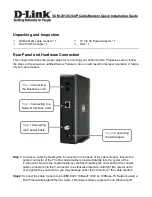
Page 226: ...is 21 333ksps and the occupied bandwidth would be approximately 28KHz 3dB power point Notice that the carrier is centered at exactly 70MHz This is typically what you would see if you simply set the m...

Page 227: ...rier identification to avoid a false lock condition With this 1KHz offset and a symbol rate of 21 333ksps the modem will acquire this carrier within 20 seconds At that time the value of receive offset...

Page 228: ...the carrier offset known the demodulator shifts its center frequency to compensate for any difference between the value of RS and the actual carrier frequency Unless the operator sets the modem back t...

Reviews: