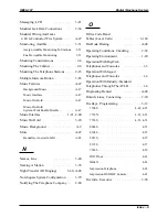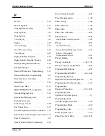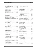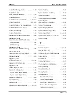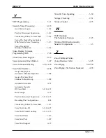
Caller ID . . . . . . . . . . . . . . . A-15–16
Caller ID Parameter
Switches, Setting . . . . . . . . . . . . 2-74
Caller ID Service Support . . . . . . .
3-165
Assigning A “SAVE” Button
(optional programming) . . . . . . . . . 3-170
Assigning Caller ID Lines
(required programming) . . . . . . . . . 3-168
Assigning Caller ID Stations
(required programming) . . . . . . . . . 3-168
Configuration Chart . . . . . . . . . . . . 4-2
Configuring RS232 Data Port B
(required programming) . . . . . . . . . 3-169
Setting The Audible First Ring Feature
(optional programming) . . . . . . . . . 3-169
Setting The Caller ID Distribution
(optional programming) . . . . . . . . . 3-170
Caller Identification
Service, Supporting . . . . . . . . . . . 2-74
Calling Records, Direct Department . . 4-22
Calling Station
Identification On BLF . . . . . . . . . . A-16
Central Message Desk . . . . . . . . . . 3-56
Central Office Limits . . . . . . . . . . 1-21
Central Office Lines . . . . . . . . . . . 3-42
Checking The General
Operating Conditions . . . . . . . . . . 2-52
Checking The Resistance . . . . . . . . 2-51
Checking The System Installation . . . . 2-51
Checking The System
Status Indicator . . . . . . . . . . . . . 2-53
Checking The Voltage . . . . . . . . . . 2-51
Class Of Service . . . . . . . . . . . A-16–18
Clearing The System . . . . . . . 2-50, 3-12
Clock . . . . . . . . . . . . . . . . . . 3-27
Common Audible
And Auxiliary Ringing Interface
. . . . 2-30
Common Audible Ringer Interface . . . A-18
Common Equipment
Data Connections . . . . . . . . . . . . 2-36
Common Equipment Description . . . . . 1-8
Conferencing
. . . . . . . . . . . . . . A-18
Add-On Conferencing . . . . . . . . . . A-18
Multiline Conferencing . . . . . . . . . A-18
Unsupervised Conferencing . . . . . . . A-18
Configuration Records, System . . . . . . 4-3
Connecting A
Power Failure Station . . . . . . . . . . 2-28
Connecting Data Devices . . . . . . . . 2-34
Connecting Outside Lines . . . . . . . . 2-30
Connecting Selected Ports . . . . . . . . 2-30
Connecting Stations
To The Expansion Module . . . . . . . . 2-43
ConnectingStations
To The G0408 . . . . . . . . . . . . . . 2-19
Connecting Stations
To The G0816 . . . . . . . . . . . . . . 2-20
Connecting Stations
To The G1632 . . . . . . . . . . . . . . 2-21
Connecting The Lines . . . . . . . . . . 2-12
Connecting The Stations . . . . . . . . . 2-16
Connection, Power . . . . . . . . . . . . . 2-8
Console Support . . . . . . . . . . . . . A-19
Converting Button Designations . . . . . . 3-9
Creating A Static Safe Work Area . . . . 2-46
IMI66–107
Digital Telephone System
Index – 3
Summary of Contents for Air Impact DSU
Page 2: ...Printed in U S A GCA47 157 ...
Page 30: ......
Page 112: ......
Page 192: ...Digital Telephone System IMI66 107 3 80 System Programming ...
Page 283: ......
Page 284: ......
Page 285: ......
Page 286: ......
Page 287: ......
Page 288: ......
Page 289: ......
Page 290: ......
Page 291: ......
Page 292: ......
Page 293: ......
Page 294: ......
Page 295: ......
Page 296: ......
Page 297: ......
Page 298: ......
Page 299: ......
Page 300: ......
Page 301: ......
Page 302: ......
Page 303: ......
Page 304: ......
Page 305: ......
Page 306: ......
Page 307: ......
Page 308: ......
Page 309: ......
Page 310: ......
Page 311: ......
Page 312: ......
Page 313: ......
Page 314: ......
Page 315: ......
Page 316: ......
Page 317: ......
Page 318: ......
Page 319: ......
Page 320: ......
Page 321: ......
Page 322: ......
Page 323: ......
Page 324: ......
Page 325: ......
Page 326: ......
Page 327: ......
Page 328: ......
Page 329: ......
Page 330: ......
Page 331: ......
Page 332: ......
Page 333: ......
Page 334: ......
Page 335: ......
Page 336: ......
Page 337: ......
Page 338: ......
Page 339: ......
Page 340: ......
Page 431: ......
Page 436: ......
Page 437: ......
Page 438: ......


