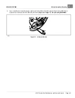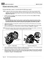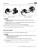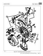
ACCELERATOR AND BRAKE PEDAL GROUP
Pedal Group Adjustment – Electric Vehicles
5
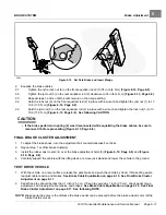
bumper upward decreases distance between pedal and floorboard. Adjusting the bumper downward
increases distance between pedal and floorboard. Proper brake pedal height is 6 inches (15.2 cm)
2.4.
Tighten the jam nut (31) to 8 ft·lb (9.5 N·m)
22
31
PA
RK
ST
OP
1 2
3
4
5
6
7
8
9
10 11
12
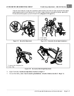
Correct pedal position is 6 inches (15.2 cm) from floormat to back of
brake pedal.
1400-18000-10211
Figure 5-8
Brake Pedal Height Adjustment
1400-18000-10212
Figure 5-9
Brake Pedal Height Measurement
3.
Adjust brake pedal free play.
See following NOTE.
NOTE:
Brake pedal free play is the distance the brake pedal can be pressed before the brake actuator arm (at the
brake cluster) moves.
3.1.
Measure perpendicularly from the floorboard to the back of the brake pedal, then press the brake pedal
and measure the distance that the pedal moves before all of the slack is taken out of the brake cables
.
3.2.
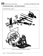
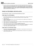
Tighten the nut (2) on the equalizer rod (1) so that the brake pedal free play is 1/4 inch to 1/2 inch (6.3 mm
to 12.7 mm)
3.3.
Tighten the jam nut (3) while holding the adjustment nut (2) in the correct position.
4.
Adjust park brake ratchet/pawl gap and pawl engagement.
4.1.
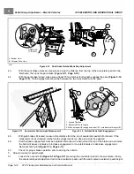
Inspect the park brake pawl (1) and ratchet (2) for excessive wear, grooves, cracks, or chips
. If either the pawl or ratchet is damaged, both must be replaced.
4.2.
Adjust retaining nut (3) on spring support rod until there is a 0.060 inch (1.5 mm) gap between the pawl
and the tips of the ratchet teeth. Use a feeler gauge to verify the gap
. The gap
should be consistent through range of pawl movement. If the gap is not consistent, loosen the four bolts (4)
securing the accelerator pivot rod supports and adjust the supports. If the gap becomes smaller as the
park brake pedal is pressed, move the pivot rod supports slightly rearward until the gap is consistent. If
the gap becomes larger as the park brake pedal is pressed, move the pivot rod supports slightly forward
until gap is consistent.
2019 Transporter Maintenance and Service Manual
Page 5-9
Summary of Contents for TransPorter 4
Page 2: ......
Page 271: ...ELECTRIC MAIN HARNESS Wiring Diagrams Electric Main Harness 18 ...
Page 272: ... Page intentionally left blank ...
Page 273: ...ELECTRIC INSTRUMENT PANEL HARNESS Wiring Diagrams Electric Instrument Panel Harness 18 ...
Page 274: ... Page intentionally left blank ...
Page 275: ...ELECTRIC ACCESSORIES HARNESS Wiring Diagrams Electric Accessories Harness 18 ...
Page 276: ... Page intentionally left blank ...
Page 282: ...NOTES ...
Page 283: ...NOTES ...
Page 284: ...NOTES ...
Page 285: ......
Page 286: ......


