MOTOR
Motor Installation
16
A
B
1
3
4
2
5
2
5
1
4
3
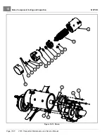
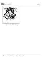
A. End View B. Side View
3066
Figure 16-16
Speed Sensor Clamp
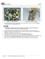
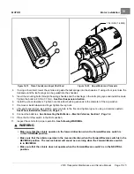
MOTOR INSTALLATION
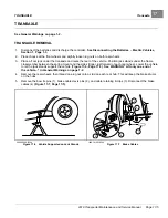
See General Warnings on page 1-2.
1.
Clean the transaxle input shaft.
1.1.
Spray the input shaft thoroughly with CRC
®
Brakleen™ or equivalent brake cleaner degreaser.
1.2.
Wipe input shaft with a clean cloth.
1.3.
Inspect the grooves of the input shaft and remove any remaining debris.
1.4.
Repeat steps 1.1 through 1.3 until input shaft is clean.
2.
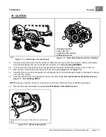
Lubricate the transaxle input shaft.
2.1.
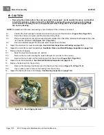
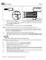
Squeeze approximately 1/2 inch (1.3 cm) of moly-teflon lubricant from tube onto a putty knife as shown
.
2.2.
Rotate wheels to rotate input shaft.
2.3.
Apply motor coupling grease evenly to the rotating input shaft starting at approximately 1/8 inch (3.1
mm) from the end of the shaft and working back toward the transaxle (away from the end of the shaft)
.
2.4.
The grease should be evenly distributed in the grooves to a width of approximately 3/8 inch (9.5 mm).
2.5.
Use a flat screwdriver to clean the grease out of one of the grooves and allow air to escape when the
motor is pushed onto the input shaft.
2019 Transporter Maintenance and Service Manual
Page 16-13
Summary of Contents for TransPorter 4
Page 2: ......
Page 271: ...ELECTRIC MAIN HARNESS Wiring Diagrams Electric Main Harness 18 ...
Page 272: ... Page intentionally left blank ...
Page 273: ...ELECTRIC INSTRUMENT PANEL HARNESS Wiring Diagrams Electric Instrument Panel Harness 18 ...
Page 274: ... Page intentionally left blank ...
Page 275: ...ELECTRIC ACCESSORIES HARNESS Wiring Diagrams Electric Accessories Harness 18 ...
Page 276: ... Page intentionally left blank ...
Page 282: ...NOTES ...
Page 283: ...NOTES ...
Page 284: ...NOTES ...
Page 285: ......
Page 286: ......


