ELECTRICAL COMPONENTS
Run/Tow Switch
13
WARNING
• Make sure that the vehicle operates in the forward direction when the Forward/Reverse switch is
in the FORWARD position.
• Make sure that the vehicle operates in the reverse direction when the Forward/Reverse switch is in the
REVERSE position. The reverse buzzer will sound as a warning when the Forward/Reverse switch
is in REVERSE.
• Make sure that the vehicle does not operate when the Forward/Reverse switch is in the NEUTRAL
position.
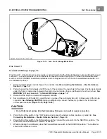
RUN/TOW SWITCH
See General Warnings on page 1-2.
TESTING THE Run/Tow SWITCH
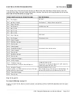
See Test Procedure 3 – Run/Tow Switch on page 12-15.
RUN/TOW SWITCH REMOVAL
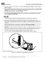
1.
Disconnect the batteries and discharge the controller.
See Disconnecting the Batteries – Electric Vehicles,
2.
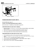
Using a 5/8 in (16 mm) socket, remove Run/Tow switch boot/hex nut (6).
3.
Remove Run/Tow switch (10) and nut (9) from bracket (5).
4.
Disconnect the two-pin connector (7) and remove switch.
RUN/TOW SWITCH INSTALLATION
1.
Installation is reverse of removal. Make sure groove on switch is aligned with tang on bracket. Tighten Run/Tow
switch boot/hex nut (6) to 16 in·lb (1.8 N·m).
2.
Connect the batteries.
See Connecting the Batteries – Electric Vehicles, Section 1, Page 1-4.
2019 Transporter Maintenance and Service Manual
Page 13-3
Summary of Contents for TransPorter 4
Page 2: ......
Page 271: ...ELECTRIC MAIN HARNESS Wiring Diagrams Electric Main Harness 18 ...
Page 272: ... Page intentionally left blank ...
Page 273: ...ELECTRIC INSTRUMENT PANEL HARNESS Wiring Diagrams Electric Instrument Panel Harness 18 ...
Page 274: ... Page intentionally left blank ...
Page 275: ...ELECTRIC ACCESSORIES HARNESS Wiring Diagrams Electric Accessories Harness 18 ...
Page 276: ... Page intentionally left blank ...
Page 282: ...NOTES ...
Page 283: ...NOTES ...
Page 284: ...NOTES ...
Page 285: ......
Page 286: ......

