ELECTRICAL COMPONENTS
Lockout Relay
13
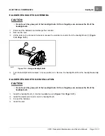
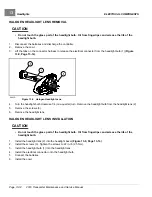
LED HEADLIGHT REMOVAL
1.
Disconnect the batteries and discharge the controller.
2.
Remove the cowl.
3.
Lift the tabs on the connector harness to release the electrical connector from the LED headlight (1)
2993E
Figure 13-10
LED Headlight
4.
Remove the screws (2).
5.
Remove the LED headlight.
LED HEADLIGHT INSTALLATION
1.
Install the LED headlight (1) into the headlight bezel
.
2.
Install the screws (2). Tighten the screws to 22 in·lb (2.5 N·m).
3.
Install the electrical connector onto the LED headlight.
4.
Connect the batteries.
5.
Install the cowl.
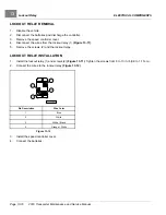
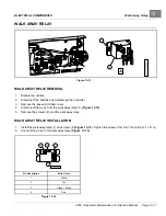
LOCKOUT RELAY
Figure 13-11
2019 Transporter Maintenance and Service Manual
Page 13-15
Summary of Contents for TransPorter 4
Page 2: ......
Page 271: ...ELECTRIC MAIN HARNESS Wiring Diagrams Electric Main Harness 18 ...
Page 272: ... Page intentionally left blank ...
Page 273: ...ELECTRIC INSTRUMENT PANEL HARNESS Wiring Diagrams Electric Instrument Panel Harness 18 ...
Page 274: ... Page intentionally left blank ...
Page 275: ...ELECTRIC ACCESSORIES HARNESS Wiring Diagrams Electric Accessories Harness 18 ...
Page 276: ... Page intentionally left blank ...
Page 282: ...NOTES ...
Page 283: ...NOTES ...
Page 284: ...NOTES ...
Page 285: ......
Page 286: ......


