ACCELERATOR AND BRAKE PEDAL GROUP
Brake Pedal and Park Brake
5
ST
OP
10
2999
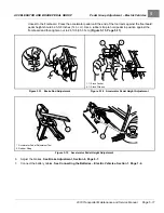
Figure 5-2
Brake Pedal Weldment Through Floor
3.
Position and attach brake pedal assembly, mounting blocks (3 and 8), and washers (10) to vehicle frame as
shown. Tighten the bolts (11) and nuts to 95 in·lb (10.7 N·m).
4.
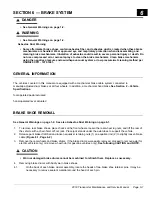
Tighten the nut (2) on the equalizer rod (1) so that brake pedal free-play is from 1/4 inch to 1/2 inch (6 mm to 13
mm)
See following NOTE.
NOTE:
Brake pedal free-play is the distance the brake pedal can be pressed before the brake actuator arm moves.
5.
Tighten the jam nut (3) while holding the adjustment nut (2) in the correct position.
6.
Adjust the pedal group. Refer to the appropriate adjustment procedure:
–
For gasoline vehicles, see .
–
For electric vehicles, see Pedal Group Adjustment – Electric Vehicles on page 5-8.
A
1
2
3
Dimension A: 1/4 inch to 1/2 inch (6 mm to 13 mm)
Note: Equalizer bracket may be inverted on some vehicles.
1369
Figure 5-3
Brake Pedal Free-Play Adjustment
2019 Transporter Maintenance and Service Manual
Page 5-3
Summary of Contents for TransPorter 4
Page 2: ......
Page 271: ...ELECTRIC MAIN HARNESS Wiring Diagrams Electric Main Harness 18 ...
Page 272: ... Page intentionally left blank ...
Page 273: ...ELECTRIC INSTRUMENT PANEL HARNESS Wiring Diagrams Electric Instrument Panel Harness 18 ...
Page 274: ... Page intentionally left blank ...
Page 275: ...ELECTRIC ACCESSORIES HARNESS Wiring Diagrams Electric Accessories Harness 18 ...
Page 276: ... Page intentionally left blank ...
Page 282: ...NOTES ...
Page 283: ...NOTES ...
Page 284: ...NOTES ...
Page 285: ......
Page 286: ......

