


Section 4 — Commissioning
4-2
Part No. 750-363
4.1 OPERATING CONDITIONS
• The installation site should be as free as possible from vibration, dust, and corrosive media
• The controllers should be located as far as possible from sources of
electromagnetic fields, such as frequency converters or high-voltage
ignition transformers
• Control panel must be connected to earth ground.
• Refer to Section 3 in this manual for combustion air requirements.
4.2 FILLING BOILER
The system should be flushed, preferably with the boiler isolated, before operating the boiler.
When filling the boiler and/or hydronic system, water should be circulated to allow entrapped air to escape
at appropriate air venting provisions. Check to ensure that no leaks appear at any pipe connections and
correct if water leaks are noticed. When no air remains in the boiler, it will be possible to reset the low water
cutoff. If the low water cutoff can not be reset, it is likely that some air remains in the boiler.
4.3 CONTROL SETPOINTS
Preliminary settings of the burner/boiler safety controls are necessary for the initial starting of the boiler.
After the burner has been properly set, minor adjustments to these controls may be necessary for the
particular installation. For initial starting, set the following controls accordingly:
1. Combustion Air Proving Switch - Set the dial @ minimum.
2. Low Gas Pressure Switch - Set the dial @ minimum.
3. High Gas Pressure Switch - Set the dial @ maximum.
4. High Air Pressure Switch - Set the dial @ maximum (for operational settings see Table 4-2).
Depress all manual reset buttons for all controls prior to starting.
Note: Ensure that the post-startup checkout procedure (section 4.11) is observed following
commissioning.
Boiler room ambient conditions
Relative humidity
< 85% non-condensing
Ambient temperature range
0
o
C to 50
o
C / 32
o
F to 122
o
F
Storage temperature range
-40
o
C to 60
o
C / -40
o
F to 140
o
F
Combustion air temperature
0
o
C to 50
o
C / 32
o
F to 122
o
F
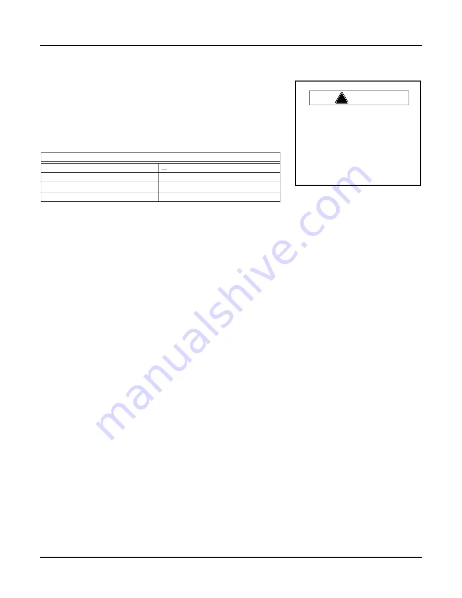
!
Warning
W h e n u s i n g d i r e c t v e n t
combustion in cold climates,
special care must be taken to
o b s e r v e c o m b u s t i o n a i r
temperature limits.
Failure to
follow this precaution may lead
to equipment damage or unsafe
operation.
Summary of Contents for ClearFire CFLC Series
Page 6: ...vi...
Page 14: ...Section 1 Introduction 1 8 Part No 750 363...
Page 16: ...Section 2 Installation 2 2 Part No 750 363...
Page 36: ...Section 2 Installation 2 22 Part No 750 363 Figure 2 13 Electrical Connections CFLC FALCON...
Page 38: ...Section 2 Installation 2 24 Part No 750 363...
Page 56: ...Section 3 Stack and Intake Vent Sizing and Installation 3 18 Part No 750 363...
Page 87: ...Section 6 Parts Part No 750 363 6 3 Figure 6 1 Boiler Mechanical Assembly CFLC 4000 5000...
Page 88: ...Section 6 Parts 6 4 Part No 750 363 Figure 6 2 Boiler Mechanical Assembly CFLC 6000 8000...
Page 95: ...Section 6 Parts Part No 750 363 6 11 Figure 6 10 Gas Train CFLC 6000 8000 optional 9 PPM NOx...
Page 97: ...Section 6 Parts Part No 750 363 6 13 Figure 6 12 Gas train CFLC 10000 12000 optional 9 PPM NOx...
Page 98: ...Section 6 Parts 6 14 Part No 750 363 Figure 6 13 Gas Train CFLC 4000 5000 Propane...
Page 99: ...Section 6 Parts Part No 750 363 6 15 Figure 6 14 Gas Train CFLC 6000 8000 Propane...
Page 100: ...Section 6 Parts 6 16 Part No 750 363 Figure 6 15 Gas Train CFLC 10000 12000 Propane...
Page 105: ...Section 6 Parts Part No 750 363 6 21 Figure 6 20 Control Panel...
Page 106: ...Section 6 Parts 6 22 Part No 750 363 Figure 6 21 Cables and Cable Harness...
Page 108: ...Section 6 Parts 6 24 Part No 750 363 Figure 6 23 Casing Insulation 4000 5000 cont d...
Page 109: ...Section 6 Parts Part No 750 363 6 25 Figure 6 24 Casing Insulation 6000 8000...
Page 110: ...Section 6 Parts 6 26 Part No 750 363 Figure 6 25 Casing Insulation 6000 8000 cont d...
Page 115: ...APPENDIX A Falcon Parameters...
Page 116: ......
Page 124: ......
Page 144: ......
Page 145: ...APPENDIX C Gas Valve Page C 3 Siemens Gas Valve Page C 25 Dungs Gas Valve CFLC 4000 5000...
Page 146: ......
Page 147: ...Appendix C Gas Valve C 3...
Page 148: ...Gas Valve Appendix C C 4...
Page 149: ...Appendix C Gas Valve C 5...
Page 150: ...Gas Valve Appendix C C 6...
Page 151: ...Appendix C Gas Valve C 7...
Page 152: ...Gas Valve Appendix C C 8...
Page 153: ...Appendix C Gas Valve C 9...
Page 154: ...Gas Valve Appendix C C 10...
Page 155: ...Appendix C Gas Valve C 11...
Page 156: ...Gas Valve Appendix C C 12...
Page 157: ...Appendix C Gas Valve C 13...
Page 158: ...Gas Valve Appendix C C 14...
Page 159: ...Appendix C Gas Valve C 15...
Page 160: ...Gas Valve Appendix C C 16...
Page 161: ...Appendix C Gas Valve C 17...
Page 162: ...Gas Valve Appendix C C 18...
Page 163: ...Appendix C Gas Valve C 19...
Page 164: ...Gas Valve Appendix C C 20...
Page 165: ...Appendix C Gas Valve C 21...
Page 166: ...Gas Valve Appendix C C 22...
Page 167: ...Appendix C Gas Valve C 23...
Page 168: ...Appendix C Gas Valve C 24...
Page 186: ...Appendix C Gas Valve C 42...
Page 187: ...APPENDIX D Falcon Alert Hold and Lockout Codes...
Page 188: ......
Page 208: ......
Page 210: ......
Page 231: ...Appendix E Falcon Lead Lag E 23 Figure 11 Falcon LL with EMS for remote enable remote setpoint...
Page 232: ...Falcon Lead Lag Appendix E E 24 Figure 12 Falcon Lead Lag with EMS for remote comms monitoring...
Page 245: ...Appendix E Falcon Lead Lag E 37 Model CFW ClearFire hydronic boiler...
Page 282: ......
Page 283: ...APPENDIX F Falcon Program Module...
Page 284: ......
Page 285: ...Appendix F Program Module F 3...
Page 286: ...Program Module Appendix F F 4...
Page 287: ...Appendix F Program Module F 5...
Page 288: ...Program Module Appendix F F 6...
Page 289: ......
Page 290: ...e mail info cleaverbrooks com Web Address http www cleaverbrooks com...