


Appendix C
Gas Valve
C-30
7. Tighten the scr ews on the metal strain relief.
The maximum tor que for each metal str ain relief scr ew
is 4.4 in-lb (0.5 Nm).
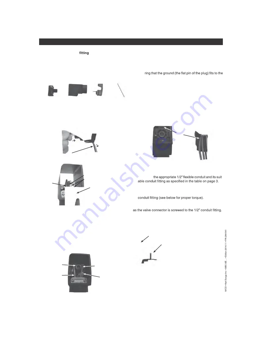
8. Assemble
-
9. R oute the “pig-tailed” wires from the valve connector
through the 1/2” conduit and to the nearest conduit body
(panel), and then screw the valve connector to the 1/2”
NOTE:
It may be necessary to pull the wires at the nearest
conduit body to reduce any potential wire slack in the raceway
10. Assemble the cover and mounting screw to the valve con -
nector, and mount the valve connector to the valve coil as
shown below.
11. Tighten the mounting scr ew.
12. Follow NEC (NFPA 70) requirements for proper termination
at the nearest conduit body.
Failure to follow the exact instructions belo w ma y result
in a valve connector not
to valve.
STEPS
1. After selecting the pr oper number of wires, push the mount -
ing screw completely out from the valve connector and
disassemble the remaining 4 parts as shown below:
2. Star ting from the 1/2” NPT end of the housing, push the
wires under the metal strain relief and through the housing
(see FIG. A below). The GREEN (ground) wire should be
placed into the far left groove when viewed as shown in
FIG. B. The “Neutral (-) ” should be placed into the groove
next to the GREEN (ground).
3. Continue to push the wir es through the housing until there
is at least an extra 3”- 6”available for connecting the wires
to the terminals on the T-Block (see FIG. A above).
4. Strip no mor e than 1/4” of insulation from each wire.
5. Wiring to the corr ect terminal is critical. The terminals are
labeled next to the terminal screws. Terminate each wire to
its proper terminal on the T-block. See FIG. C to determine
the proper terminals for the valve. NOTE: One neutral is
used to power both valves.
Mounting Screw
Terminal Block
(T-Block)
Cover
The maximum torque at the 1/2” NPT conduit
housing connection is
60 in-lb (6.75 Nm).
Fig. A
Strip the end of each
lead 1/4” maximum
push wi
res
pull 3”-6”
of e
xtr
a wir
e
Neutral
-
Metal Strain
Relief
Ground
Fig. B
Fig. D
Ground
Fig. E
The maximum torque for mounting
screw is 8.8 in-lb (1.0 Nm).
Housing
The maximum tor que for the terminal scr ews is 4.4 in-lb
(0.5 Nm).
6. Pull the wires so that the T-Block is completely pulled into
the housing. As the T-Block gets pulled into the housing,
the T-Block and the wires must be properly guided into the
housing by:
A) Ensu
front of the housing as shown in FIG. D below,
AND
B) Ensu ring that the wires lay side-by-side beneath the metal
strain relief as shown in Fig. E below,
AND
C) Organizing the wires so that they terminate on the same
side of the connector under which they were routed. The
wires must NOT crisscross inside the housing to the op
-
posite side from which they are terminated. Fig. C illustrates
how the wires terminate on the same side under which they
were routed.
Terminal #2
Hot (+) for valve #1
Terminal #3
Hot (+) for valve #2
Ground
Terminal #1
Neutral (-)
Fig. C
Hot
+
Electrical DIN Connector assembly & wiring
Summary of Contents for ClearFire CFLC Series
Page 6: ...vi...
Page 14: ...Section 1 Introduction 1 8 Part No 750 363...
Page 16: ...Section 2 Installation 2 2 Part No 750 363...
Page 36: ...Section 2 Installation 2 22 Part No 750 363 Figure 2 13 Electrical Connections CFLC FALCON...
Page 38: ...Section 2 Installation 2 24 Part No 750 363...
Page 56: ...Section 3 Stack and Intake Vent Sizing and Installation 3 18 Part No 750 363...
Page 87: ...Section 6 Parts Part No 750 363 6 3 Figure 6 1 Boiler Mechanical Assembly CFLC 4000 5000...
Page 88: ...Section 6 Parts 6 4 Part No 750 363 Figure 6 2 Boiler Mechanical Assembly CFLC 6000 8000...
Page 95: ...Section 6 Parts Part No 750 363 6 11 Figure 6 10 Gas Train CFLC 6000 8000 optional 9 PPM NOx...
Page 97: ...Section 6 Parts Part No 750 363 6 13 Figure 6 12 Gas train CFLC 10000 12000 optional 9 PPM NOx...
Page 98: ...Section 6 Parts 6 14 Part No 750 363 Figure 6 13 Gas Train CFLC 4000 5000 Propane...
Page 99: ...Section 6 Parts Part No 750 363 6 15 Figure 6 14 Gas Train CFLC 6000 8000 Propane...
Page 100: ...Section 6 Parts 6 16 Part No 750 363 Figure 6 15 Gas Train CFLC 10000 12000 Propane...
Page 105: ...Section 6 Parts Part No 750 363 6 21 Figure 6 20 Control Panel...
Page 106: ...Section 6 Parts 6 22 Part No 750 363 Figure 6 21 Cables and Cable Harness...
Page 108: ...Section 6 Parts 6 24 Part No 750 363 Figure 6 23 Casing Insulation 4000 5000 cont d...
Page 109: ...Section 6 Parts Part No 750 363 6 25 Figure 6 24 Casing Insulation 6000 8000...
Page 110: ...Section 6 Parts 6 26 Part No 750 363 Figure 6 25 Casing Insulation 6000 8000 cont d...
Page 115: ...APPENDIX A Falcon Parameters...
Page 116: ......
Page 124: ......
Page 144: ......
Page 145: ...APPENDIX C Gas Valve Page C 3 Siemens Gas Valve Page C 25 Dungs Gas Valve CFLC 4000 5000...
Page 146: ......
Page 147: ...Appendix C Gas Valve C 3...
Page 148: ...Gas Valve Appendix C C 4...
Page 149: ...Appendix C Gas Valve C 5...
Page 150: ...Gas Valve Appendix C C 6...
Page 151: ...Appendix C Gas Valve C 7...
Page 152: ...Gas Valve Appendix C C 8...
Page 153: ...Appendix C Gas Valve C 9...
Page 154: ...Gas Valve Appendix C C 10...
Page 155: ...Appendix C Gas Valve C 11...
Page 156: ...Gas Valve Appendix C C 12...
Page 157: ...Appendix C Gas Valve C 13...
Page 158: ...Gas Valve Appendix C C 14...
Page 159: ...Appendix C Gas Valve C 15...
Page 160: ...Gas Valve Appendix C C 16...
Page 161: ...Appendix C Gas Valve C 17...
Page 162: ...Gas Valve Appendix C C 18...
Page 163: ...Appendix C Gas Valve C 19...
Page 164: ...Gas Valve Appendix C C 20...
Page 165: ...Appendix C Gas Valve C 21...
Page 166: ...Gas Valve Appendix C C 22...
Page 167: ...Appendix C Gas Valve C 23...
Page 168: ...Appendix C Gas Valve C 24...
Page 186: ...Appendix C Gas Valve C 42...
Page 187: ...APPENDIX D Falcon Alert Hold and Lockout Codes...
Page 188: ......
Page 208: ......
Page 210: ......
Page 231: ...Appendix E Falcon Lead Lag E 23 Figure 11 Falcon LL with EMS for remote enable remote setpoint...
Page 232: ...Falcon Lead Lag Appendix E E 24 Figure 12 Falcon Lead Lag with EMS for remote comms monitoring...
Page 245: ...Appendix E Falcon Lead Lag E 37 Model CFW ClearFire hydronic boiler...
Page 282: ......
Page 283: ...APPENDIX F Falcon Program Module...
Page 284: ......
Page 285: ...Appendix F Program Module F 3...
Page 286: ...Program Module Appendix F F 4...
Page 287: ...Appendix F Program Module F 5...
Page 288: ...Program Module Appendix F F 6...
Page 289: ......
Page 290: ...e mail info cleaverbrooks com Web Address http www cleaverbrooks com...