


Section 2 — Installation
Part No. 750-363
2-7
Typically, ethylene glycol is used for freeze protection, but other alternatives exist, such as propylene glycol.
Glycol reduces the water-side heat capacity (lower specific heat than 100% water) and can reduce the
effective heat transfer to the system. Because of this, design flow rates and pump selections should be sized
with this in mind.
Generally, corrosion inhibitors are added to glycol systems. However, all glycols tend to oxidize over time in
the presence of oxygen, and when heated, form aldehydes, acids, and other oxidation products. Whenever
inadequate levels of water treatment buffers and corrosion inhibitors are used, the resulting water glycol
mixture pH may be reduced to below 7.0 (frequently reaching 5) and acid corrosion results. Thus, when
pH levels drop below 7.0 due to glycol degradation the only alternative is to drain, flush, repassivate, and
refill with a new inhibited glycol solution.
The following recommendations should be adhered to in applying ClearFire model CFLC boilers to hydronic
systems using glycol:
1)
Maximum allowable antifreeze proportion (% volume):
50% antifreeze (glycol)
50% water
2)
Glycol minimum temperature rating 300 deg F (149 deg C).
3)
Maximum allowable boiler outlet/supply temperature: 200 deg F (93 deg C).
4)
Minimum water circulation through the boiler:
a)
The minimum water circulation must be defined in such a way that the temperature difference between the boiler
outlet/supply and inlet/return is a maximum of 40 deg F (22 deg C), defined as
D
T (Delta T). A
D
T Limit algorithm
should be enabled in the boiler controller.
b)
Independent from the hydraulics of the heating system, regular water circulation through each boiler is required
while the boiler is operating (requires a dedicated boiler pump if in a primary/secondary loop arrangement). Refer
to table below for minimum boiler circulation rates.
5)
Minimum over-pressure at the boiler:
For outlet temperatures up to the maximum of 200 deg F (93 deg C), a minimum operating pressure of 30 psig (2.1 bar) is
required.
6)
pH level should be maintained between 8.3 and 10.5
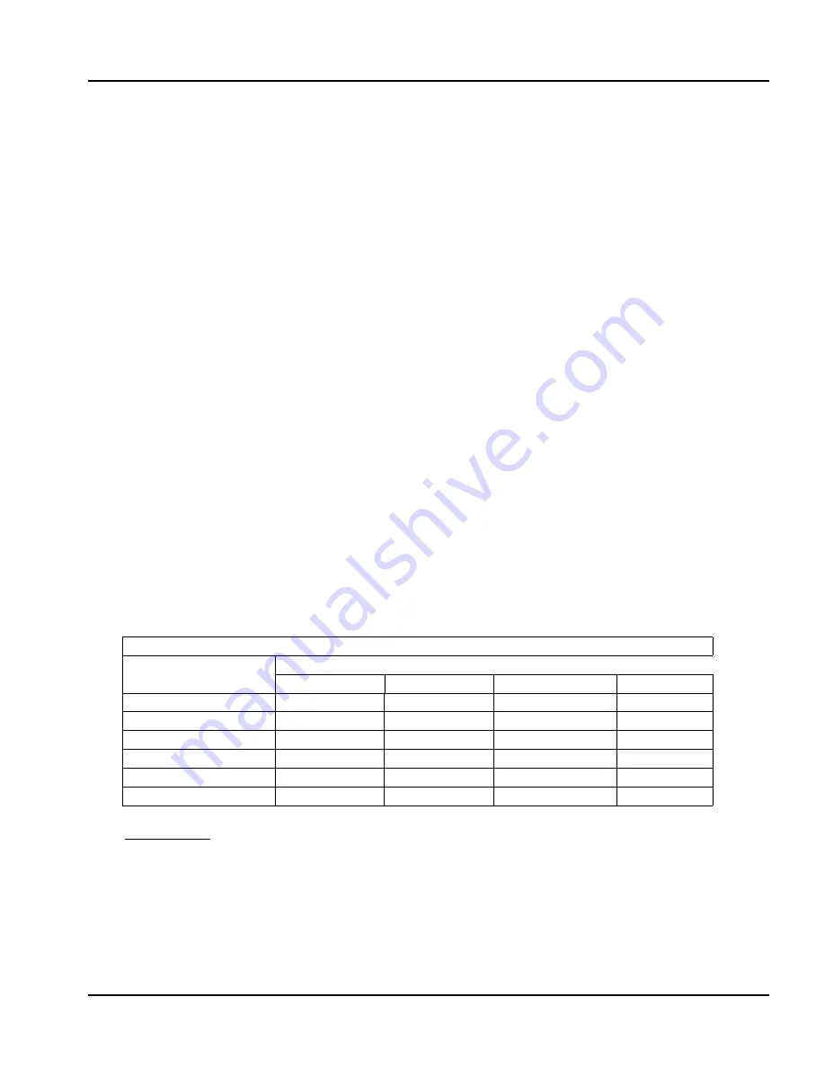
Table 2-4 Glycol Application Guidelines — ClearFire Model CFLC
Minimum required boiler circulation rate (gpm) at maximum firing rate
ClearFire
Model-Size
System
Δ
T (
˚
F)
Δ
T = 10
˚
Δ
T = 20
˚
Δ
T = 30
˚
Δ
T = 40
˚
CFLC-4000
813
407
271
203
CFLC-5000
1016
508
339
254
CFLC-6000
1220
610
374
281
CFLC-8000
1626
813
499
368
CFLC-10000
2033
1016
624
468
CFLC-12000
2439
1220
749
562
Notes/Limitations:
1. Glycol concentration limit of 25%-50%. Minimum required system operating pressure is 30 psig.
2. Maximum system operating temperature of 200
˚
F. Maximum
Δ
T of 40
˚
.
3. Circulation rates correlate with boiler output based on 92% nominal efficiency.
4. Standard altitude (<2000' ASL). Contact C-B for high altitude applications.
5. Pumps should be sized based on system design
Δ
T and minimum required flow rates.
6. At minimum firing rate, the minimum circulation rate should correspond to the boiler's turndown.
Summary of Contents for ClearFire CFLC Series
Page 6: ...vi...
Page 14: ...Section 1 Introduction 1 8 Part No 750 363...
Page 16: ...Section 2 Installation 2 2 Part No 750 363...
Page 36: ...Section 2 Installation 2 22 Part No 750 363 Figure 2 13 Electrical Connections CFLC FALCON...
Page 38: ...Section 2 Installation 2 24 Part No 750 363...
Page 56: ...Section 3 Stack and Intake Vent Sizing and Installation 3 18 Part No 750 363...
Page 87: ...Section 6 Parts Part No 750 363 6 3 Figure 6 1 Boiler Mechanical Assembly CFLC 4000 5000...
Page 88: ...Section 6 Parts 6 4 Part No 750 363 Figure 6 2 Boiler Mechanical Assembly CFLC 6000 8000...
Page 95: ...Section 6 Parts Part No 750 363 6 11 Figure 6 10 Gas Train CFLC 6000 8000 optional 9 PPM NOx...
Page 97: ...Section 6 Parts Part No 750 363 6 13 Figure 6 12 Gas train CFLC 10000 12000 optional 9 PPM NOx...
Page 98: ...Section 6 Parts 6 14 Part No 750 363 Figure 6 13 Gas Train CFLC 4000 5000 Propane...
Page 99: ...Section 6 Parts Part No 750 363 6 15 Figure 6 14 Gas Train CFLC 6000 8000 Propane...
Page 100: ...Section 6 Parts 6 16 Part No 750 363 Figure 6 15 Gas Train CFLC 10000 12000 Propane...
Page 105: ...Section 6 Parts Part No 750 363 6 21 Figure 6 20 Control Panel...
Page 106: ...Section 6 Parts 6 22 Part No 750 363 Figure 6 21 Cables and Cable Harness...
Page 108: ...Section 6 Parts 6 24 Part No 750 363 Figure 6 23 Casing Insulation 4000 5000 cont d...
Page 109: ...Section 6 Parts Part No 750 363 6 25 Figure 6 24 Casing Insulation 6000 8000...
Page 110: ...Section 6 Parts 6 26 Part No 750 363 Figure 6 25 Casing Insulation 6000 8000 cont d...
Page 115: ...APPENDIX A Falcon Parameters...
Page 116: ......
Page 124: ......
Page 144: ......
Page 145: ...APPENDIX C Gas Valve Page C 3 Siemens Gas Valve Page C 25 Dungs Gas Valve CFLC 4000 5000...
Page 146: ......
Page 147: ...Appendix C Gas Valve C 3...
Page 148: ...Gas Valve Appendix C C 4...
Page 149: ...Appendix C Gas Valve C 5...
Page 150: ...Gas Valve Appendix C C 6...
Page 151: ...Appendix C Gas Valve C 7...
Page 152: ...Gas Valve Appendix C C 8...
Page 153: ...Appendix C Gas Valve C 9...
Page 154: ...Gas Valve Appendix C C 10...
Page 155: ...Appendix C Gas Valve C 11...
Page 156: ...Gas Valve Appendix C C 12...
Page 157: ...Appendix C Gas Valve C 13...
Page 158: ...Gas Valve Appendix C C 14...
Page 159: ...Appendix C Gas Valve C 15...
Page 160: ...Gas Valve Appendix C C 16...
Page 161: ...Appendix C Gas Valve C 17...
Page 162: ...Gas Valve Appendix C C 18...
Page 163: ...Appendix C Gas Valve C 19...
Page 164: ...Gas Valve Appendix C C 20...
Page 165: ...Appendix C Gas Valve C 21...
Page 166: ...Gas Valve Appendix C C 22...
Page 167: ...Appendix C Gas Valve C 23...
Page 168: ...Appendix C Gas Valve C 24...
Page 186: ...Appendix C Gas Valve C 42...
Page 187: ...APPENDIX D Falcon Alert Hold and Lockout Codes...
Page 188: ......
Page 208: ......
Page 210: ......
Page 231: ...Appendix E Falcon Lead Lag E 23 Figure 11 Falcon LL with EMS for remote enable remote setpoint...
Page 232: ...Falcon Lead Lag Appendix E E 24 Figure 12 Falcon Lead Lag with EMS for remote comms monitoring...
Page 245: ...Appendix E Falcon Lead Lag E 37 Model CFW ClearFire hydronic boiler...
Page 282: ......
Page 283: ...APPENDIX F Falcon Program Module...
Page 284: ......
Page 285: ...Appendix F Program Module F 3...
Page 286: ...Program Module Appendix F F 4...
Page 287: ...Appendix F Program Module F 5...
Page 288: ...Program Module Appendix F F 6...
Page 289: ......
Page 290: ...e mail info cleaverbrooks com Web Address http www cleaverbrooks com...