


Section 3 — Stack and Intake Vent Sizing and Installation
Part No. 750-363
3-3
Vent material should be appropriate for the Appliance Category.
Application-specific information will further determine the material
selected.
For Category II, III & IV appliance categories, Cleaver-Brooks highly
recommends that the flue system be Listed to standard UL 1738
Special Gas Vent and be installed in accordance with the National
Fuel Gas Code (NFPA 54) or ANSI Z21.47/ CSA 2.3. Type B Vent
shall not be allowed for positive pressure (forced draft burner) or
condensing vent systems.
Draft calculations should be performed for any condensing boiler
flue system. It is good practice to perform calculations at several
operating conditions to ensure draft tolerances are maintained.
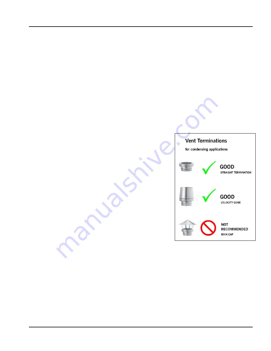
For best performance, individual, through-the-roof vertical flue
venting is recommended for CFLC boilers. Cleaver-Brooks
recommends vertical straight flue (no loss) or velocity cone flue
termination.
Note: Traditional rain caps should not be used, as moist,
condensing flue gases can be directed downward
toward the building and air intakes. In cold climates and
freezing ambient temperatures, rain caps can lead to ice
formation, air intake blockage, and flue blockage that
result from condensing water vapor in the flue gases.
Cleaver-Brooks discourages the use of horizontal through-the-wall
flue termination with CFLC boilers. Vertical flue terminations are
recommended for optimum combustion performance and building
exterior maintenance.
An active draft inducer may be necessary for a horizontal flue
arrangement that exceeds the allowable draft tolerance.
Contact the Cleaver-Brooks authorized representative for
consideration of horizontal flue termination with CFLC boilers.
3.1.3 Draft Tolerances
For Individual flue vented boilers:
Maximum allowed pressure
at vent connection is minus 0.25
inches to plus 0.10 to WC.
Recommended maximum design pressure
at vent connection is
minus 0.10 to plus 0.10 inches WC.
For common flue vented boilers:
Maximum allowed pressure
at vent connection is minus 0.25 inch
to 0.0 inch WC.
Recommended maximum design pressure
at vent connection is
minus 0.10 to 0.0 inch WC.
3.1.4 Vent Terminal Location
Give special attention to the location of the vent termination to avoid
possibility of property damage, compromised performance, or
personal injury. For best results with condensing boilers, use vertical
straight (no loss) flue discharge or velocity cone termination. These
Figure 3-1 Vent Terminations
Summary of Contents for ClearFire CFLC Series
Page 6: ...vi...
Page 14: ...Section 1 Introduction 1 8 Part No 750 363...
Page 16: ...Section 2 Installation 2 2 Part No 750 363...
Page 36: ...Section 2 Installation 2 22 Part No 750 363 Figure 2 13 Electrical Connections CFLC FALCON...
Page 38: ...Section 2 Installation 2 24 Part No 750 363...
Page 56: ...Section 3 Stack and Intake Vent Sizing and Installation 3 18 Part No 750 363...
Page 87: ...Section 6 Parts Part No 750 363 6 3 Figure 6 1 Boiler Mechanical Assembly CFLC 4000 5000...
Page 88: ...Section 6 Parts 6 4 Part No 750 363 Figure 6 2 Boiler Mechanical Assembly CFLC 6000 8000...
Page 95: ...Section 6 Parts Part No 750 363 6 11 Figure 6 10 Gas Train CFLC 6000 8000 optional 9 PPM NOx...
Page 97: ...Section 6 Parts Part No 750 363 6 13 Figure 6 12 Gas train CFLC 10000 12000 optional 9 PPM NOx...
Page 98: ...Section 6 Parts 6 14 Part No 750 363 Figure 6 13 Gas Train CFLC 4000 5000 Propane...
Page 99: ...Section 6 Parts Part No 750 363 6 15 Figure 6 14 Gas Train CFLC 6000 8000 Propane...
Page 100: ...Section 6 Parts 6 16 Part No 750 363 Figure 6 15 Gas Train CFLC 10000 12000 Propane...
Page 105: ...Section 6 Parts Part No 750 363 6 21 Figure 6 20 Control Panel...
Page 106: ...Section 6 Parts 6 22 Part No 750 363 Figure 6 21 Cables and Cable Harness...
Page 108: ...Section 6 Parts 6 24 Part No 750 363 Figure 6 23 Casing Insulation 4000 5000 cont d...
Page 109: ...Section 6 Parts Part No 750 363 6 25 Figure 6 24 Casing Insulation 6000 8000...
Page 110: ...Section 6 Parts 6 26 Part No 750 363 Figure 6 25 Casing Insulation 6000 8000 cont d...
Page 115: ...APPENDIX A Falcon Parameters...
Page 116: ......
Page 124: ......
Page 144: ......
Page 145: ...APPENDIX C Gas Valve Page C 3 Siemens Gas Valve Page C 25 Dungs Gas Valve CFLC 4000 5000...
Page 146: ......
Page 147: ...Appendix C Gas Valve C 3...
Page 148: ...Gas Valve Appendix C C 4...
Page 149: ...Appendix C Gas Valve C 5...
Page 150: ...Gas Valve Appendix C C 6...
Page 151: ...Appendix C Gas Valve C 7...
Page 152: ...Gas Valve Appendix C C 8...
Page 153: ...Appendix C Gas Valve C 9...
Page 154: ...Gas Valve Appendix C C 10...
Page 155: ...Appendix C Gas Valve C 11...
Page 156: ...Gas Valve Appendix C C 12...
Page 157: ...Appendix C Gas Valve C 13...
Page 158: ...Gas Valve Appendix C C 14...
Page 159: ...Appendix C Gas Valve C 15...
Page 160: ...Gas Valve Appendix C C 16...
Page 161: ...Appendix C Gas Valve C 17...
Page 162: ...Gas Valve Appendix C C 18...
Page 163: ...Appendix C Gas Valve C 19...
Page 164: ...Gas Valve Appendix C C 20...
Page 165: ...Appendix C Gas Valve C 21...
Page 166: ...Gas Valve Appendix C C 22...
Page 167: ...Appendix C Gas Valve C 23...
Page 168: ...Appendix C Gas Valve C 24...
Page 186: ...Appendix C Gas Valve C 42...
Page 187: ...APPENDIX D Falcon Alert Hold and Lockout Codes...
Page 188: ......
Page 208: ......
Page 210: ......
Page 231: ...Appendix E Falcon Lead Lag E 23 Figure 11 Falcon LL with EMS for remote enable remote setpoint...
Page 232: ...Falcon Lead Lag Appendix E E 24 Figure 12 Falcon Lead Lag with EMS for remote comms monitoring...
Page 245: ...Appendix E Falcon Lead Lag E 37 Model CFW ClearFire hydronic boiler...
Page 282: ......
Page 283: ...APPENDIX F Falcon Program Module...
Page 284: ......
Page 285: ...Appendix F Program Module F 3...
Page 286: ...Program Module Appendix F F 4...
Page 287: ...Appendix F Program Module F 5...
Page 288: ...Program Module Appendix F F 6...
Page 289: ......
Page 290: ...e mail info cleaverbrooks com Web Address http www cleaverbrooks com...