background image

111

FieldSmart

®

 Fiber Active Cabinet (FAC) 400

__________________________________________________________

Installation Manual

Direct: 763.476.6866 • National: 800.422.2537 • www.SeeClearfield.com • [email protected] 

Manual 020419 REV A - Feb 2019

Installing a 48-Position Fiber Distribution Panel

This topic describes how to install a 48-position fiber distribution panel. The 48-position distribution panel is comprised of 

(4) 12-position cassettes, pre-terminated to a 100-foot OSP fiber cable. The distribution cassettes install onto a mounting 

bracket that attaches to the cabinet's protection panel mounting frame. Note that the fiber distribution panel and the mount

-

ing brackets are ordered and packaged separately but installed together in the field. 

Clearfield also offers a 96-position distribution panel, which is comprised of (8) 12-position cassettes, also pre-terminated to 

a 100-foot OSP fiber cable. For 96-position panels, simply repeat the procedure for the 48-position panel below to install the 

second set of (4) cassettes into the adjacent space using a second mounting bracket. For the 96-position panel, because 

the cassettes are pre-terminated to an OSP fiber cable, the cassettes must be fed through the bracket from behind before 

the assembly is mounted. 

To install a 48-position fiber distribution panel

Step 1:

Step 2:

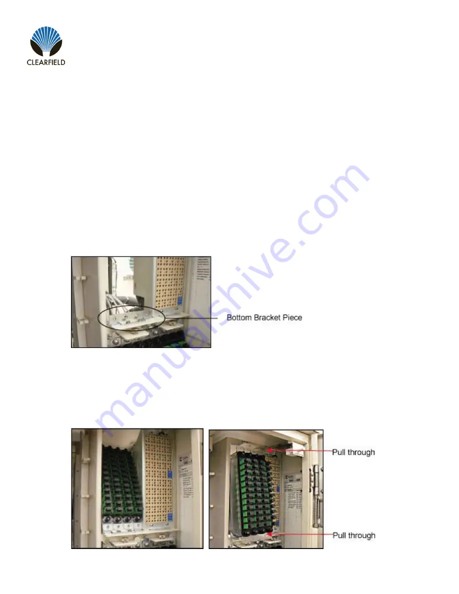
Install the bottom piece of the mounting bracket.

a. Position the bottom bracket piece on the mounting frame, aligning the holes.

b. Secure the bottom bracket piece in place using two supplied screws.

Feed the 48-position fiber distribution panel (four 12-position cassettes) through the frame opening from be

-

hind, as shown.

Summary of Contents for FieldSmart Fiber Active Cabinet 400

Page 1: ...FieldSmart Fiber Active Cabinet FAC 400 Installation Manual _______________________________________________________ Manual 020419 REV A Feb 2019 ...

Page 2: ...al Safety Recommendations 17 Installation Kit 18 User Supplied Items 19 Cabling Requirements 20 Chapter 3 Preparing the Installation Site 21 Installing a Ground Circuit 22 Constructing a Concrete Pad 25 Pad Construction Guidelines 25 Assembling the Cast In Place Template 28 Preparing the Site 29 Casting the Pad 30 Installing a Pre Cast Concrete Pad 31 Pre Cast Pad Requirements 31 Preparing the Sit...

Page 3: ... Base s 65 Installing the Cabinet on a Foundation Vault 67 Removing the Lifting Details 69 Chapter 5 Installing Local AC Power 70 Installing the Cabinet Ground Connection 71 Installing AC Power 220 240 VAC 73 Chapter 6 Installing and Splicing Outside Plant Cables 75 Bonding Cable Sheaths 76 Installing Fiber Cable 77 Installing Outside Plant Fiber Cable 77 Splicing Fibers 79 Connecting Fibers to th...

Page 4: ...ng the Fiber Management Accessories 114 Installing a 1 32 Splitter and Integration Kit 116 Chapter 9 Cabinet Maintenance 120 Routine Maintenance 121 Checking Cabinet Surfaces 121 Checking Electrical Components 122 Checking Cable Connections 123 Checking the Heat Exchanger 124 Battery Maintenance 125 Replacing Parts and Equipment 127 Removing a Cabinet Door 127 Installing a Cabinet Door 128 Replaci...

Page 5: ...easonable protection against harmful interference when the equipment is operated in a commercial environment This equipment generates uses and can radiate radio frequency energy and if not installed and used in accordance with the instruction manual may cause interference to radio communications Operation of this equipment in a residential area may cause harmful interference the user will be requi...

Page 6: ...t Overview This chapter provides a general description of the Clearfield FAC 400 outdoor cabinet including its standard features and options Topics Covered This chapter provides a general description of the Clearfield FAC 400 outdoor cabinet including its standard features and options A description of the FAC 400 cabinet A list of standard cabinet features A list of cabinet options Listed cabinet ...

Page 7: ...binet has a single compartment that houses electronics equipment together with fiber and copper plant terminations enabling deployment of multiple applications from one node The electronics area is equipped with a vertically oriented 19 inch equipment rack that provides 4 RU of mounting space The FAC 400 supports local power configurations The local power configuration includes an additional base ...

Page 8: ...rovides 4 RU of mounting space Mechanical support for fiber and copper plant terminations Modular scalable copper line protection 50 pair block increments 300 pairs maximum Door mounted 300W heat exchanger Power Local Standard features for the local power configuration include 240 VAC load center ETL listed 30 Amp capacity AC main service disconnect breaker AC surge suppressor Duplex convenience o...

Page 9: ...ity fiber management options 48 and 96 position fiber distribution panels 1 32 PON splitters management accessories up to 192 ports of internal distribution Copper line protection for up to 288 lines MS2 or 710 interface connectors Cross connect panel with MS2 or 710 interface connectors 2 1 subscriber to equipment line counts 300 pair 200 100 Clearfield xPAK low count fiber distribution with LGX ...

Page 10: ...s The external dimensions of the FAC 400 cabinet are shown below Note Based on the dimensions the cabinet can withstand 79 5 lbs of wind force Dimension Measurement SAE Measurement Metric Height Local Power 48 inches 122 cm Width 19 7 inches 60 Ah battery base 50 cm Depth 24 inches 61 cm The approximate weight of the FAC 400 cabinet is shown below Configuration Weight SAE Weight Metric Local power...

Page 11: ...ews of the FAC 400 cabinet follow Front Compartment The front compartment provides access to the electronics equipment cabinet power system and fiber management or copper line protection The cabinet power system consists of an AC load center For fiber access the fiber management accessories may vary greatly according to the ordered options For copper access the line protection may include up to si...

Page 12: ...compart ment also houses an optional cross connect panel for copper access systems Battery Compartment Local Power Cabinets configured for local power include a battery base compartment for housing one string of front access VRLA batteries Battery compartment interior dimensions for batteries 10 3 H x 18 6 W x 11 5 D inches 26 2 x 47 2 x 29 2 cm Note Batteries fit compactly in the 60 Ah base Use o...

Page 13: ...REV A Feb 2019 Chapter 2 Installation Considerations This chapter provides general considerations for cabinet installation Review this information before starting the cabinet installation process Topics Covered This chapter covers the following topics Installation process overview Installation guidelines Space requirements General safety recommendations Installation kit contents User supplied item...

Page 14: ...l __________________________________________________________ Proprietary Information Not for use or disclosure except by written agreement with Clearfield 14 Installation Process Overview The cabinet installation process involves the following high level steps ...

Page 15: ...f potential sites for subsurface conditions Grounding properties Grounding properties The earth at the cabinet location should have a low ground impedance to provide an effective grounding system for lightning protection and safety Perform ground testing to determine the grounding requirements Safety Whenever possible the cabinet should be located on vacant property away from motor traffic to redu...

Page 16: ...reement with Clearfield 16 Space Requirements The illustration below shows the cabinet clearance and space requirements The minimum clearance area around the cabinet site must be free of permanent impediments to allow full swing of the cabinet doors This area must be kept clear of obstructions at all times to provide adequate access for all installation and maintenance activities FAC 400 ...

Page 17: ...ould perform the procedures described in this doc ument These procedures involve potentially hazardous activities including handling of heavy equipment and exposure to high electrical energy which could cause injury to untrained personnel WARNING The cabinet and its components are heavy Handle with care to avoid personal injury or damage to the equipment DANGER CLASS 1 LASER PRODUCT INVISIBLE LASE...

Page 18: ...18 Installation Kit Clearfield supplies an installation kit with the cabinet that includes materials required for installation The installation kit contents are listed below Check to verify that your kit contains all of the listed items Qty Item Description 1 Telco hex key 5 16 1 Isolation mat 4 Hex nuts for mounting 8 Flat washers for mounting 4 Split lock washers for mounting 4 1 2 hex head bolt...

Page 19: ...ver bit sets Socket wrench nut driver set standard Box wrench set standard Screwdriver set standard Beam Level Insulated needle nose pliers Wire stripper Compression crimping tool Fiber cleaver Fiber splicer Modular MS2 or 710 splicing tool RB Razor Sharp Cutting Edge knife or another similar tool Materials Bring the following materials to the installation site Leveling shims Silicone sealant MS2 ...

Page 20: ...nts Cables supplied to the cabinet must meet the following minimum requirements Note Local climatic conditions site conditions or local practices may require adjustments to cabling requirements Function Facility Requirements Power Ground Copper 6 AWG solid bare copper wire to earth ground circuit terminates to ground bar with screw lug AC local power Copper 8 10 AWG stranded copper Follow National...

Page 21: ...n construct a concrete pad using the Clearfield cast in place template or use a pre cast concrete pad For pole mounting use the Clearfield pole mount kit to provide the cabinet mounting fixture A composite foundation vault available from a third party supplier can provide easy under cabinet access or serve as a riser For all mounting configurations Clearfield requires installation of an earth grou...

Page 22: ...or the NEC require ment of 25 ohms whichever is less Grounding options The cabinet main ground system must be bonded to a suitable earth ground circuit which may include any of the following Ground rod s A ground rod consists of a simple copper rod driven into the earth A ground rod connects to the main cabinet or enclosure ground via an earth ground wire bonded to the ground rod and buried at the...

Page 23: ..._________ Installation Manual Direct 763 476 6866 National 800 422 2537 www SeeClearfield com techsupport clfd net Manual 020419 REV A Feb 2019 Example of PANI compliant ground ring with main site ground buss Example of PANI compliant ground ring without a main site ground buss FAC 400 FAC 400 ...

Page 24: ...to the initial ground electrode should be a 6 AWG or larger bare cop per ground wire The ground wire should enter the cabinet separated from power or copper transmission cables Never bundle the ground wire together with other copper cables Connect the ground wire to the main ground bar Follow the PANI organization for all connections made to the equipment cabinet enclosure ground bar as shown in C...

Page 25: ...nduit locations Pad Construction Guidelines When constructing a concrete pad observe the following guidelines and refer to the pad drawings for guidance Follow these guidelines to ensure proper pad construction Adjust for local conditions or practices as required Construct the pad with minimum perimeter dimensions of 42 x 48 inches Construct the pad with a minimum height of 6 inches Construct the ...

Page 26: ...lation Manual __________________________________________________________ Proprietary Information Not for use or disclosure except by written agreement with Clearfield 26 Pad Drawings Use the following drawings for reference during pad construction ...

Page 27: ...techsupport clfd net Manual 020419 REV A Feb 2019 Pad Cross Section from left side For proper cable entry into the cabinet place conduit into the following locations a Conduit for outside plant cable copper b Conduit for outside plant cable fiber c Earth ground wire d Conduit for AC cable Use the Clearfield cast in place template to provide precise conduit orientation Conduit Locations ...

Page 28: ...ne of the short brackets using two supplied screws and nuts Step 1 Step 2 Place the four bracket members on the ground arranged as follows Place the two long brackets parallel with each other flat side down Place the two short brackets between and perpendicular to the long members flat side down with the conduit entry box bracket on the left Step 3 Assemble the Clearfield cast in place template as...

Page 29: ...ne inch above the form Verify that the form remains level across the entire surface Adjust as required Pull the earth ground wire from the conduit trench through the entry duct in the template allowing at least three feet of wire to extend above the top of the form Mask the four mounting studs on the template to protect the threads from concrete Step 1 Step 2 Step 3 Step 4 Step 5 Step 6 Step 7 Ste...

Page 30: ...ist out of shape during the pour Smooth and level the top surface of the concrete Leave the pad to cure Do not remove the form until the concrete has fully cured at least 72 hours Perform the remaining steps only after the concrete has cured Remove and discard the form Backfill the cable conduit trenches with soil or gravel as required Backfill and grade the perimeter area around the pad with soil...

Page 31: ...s and mounting fixtures threaded inserts for anchoring the cabinet to the pad Specific features and dimensions vary by manufacturer Contact your sales representative for a list of Clearfield certified suppliers Pre Cast Pad Requirements When preparing for and installing a pre cast concrete pad observe the following guidelines Refer to the pad drawings for guidance Guidelines Follow these guideline...

Page 32: ..._____________ Proprietary Information Not for use or disclosure except by written agreement with Clearfield 32 Pad Drawings Use the following drawings for reference during site preparation Actual pad dimensions may vary by manufacturer Refer to the manufacturer s documentation for more information Pad Size ...

Page 33: ...onal 800 422 2537 www SeeClearfield com techsupport clfd net Manual 020419 REV A Feb 2019 Pad Cross Section from left side For proper cable entry into the cabinet place conduit into the following locations a Conduit for outside plant cable copper b Conduit for outside plant cable fiber c Earth ground wire d Conduit for AC cable Conduit Locations ...

Page 34: ...ctrode Place gravel into the foundation hole to create a level base The gravel layer should be at least two inches deep compacted and leveled Step 1 Step 2 Step 3 Step 4 Step 5 Step 6 Prepare the site for installation of a pre cast pad Some pads may require custom preparations Refer to the manufacturer s instructions for more information A general practice is described below for reference Adapt th...

Page 35: ...evel Pull the earth ground wire through the cutout in the pad allowing at least four feet of wire to extend above the top of the pad Backfill and grade around the pad perimeter with soil to secure the pad in place Verify that the pad remains level Adjust as required Trim the cable conduits to a height no more than 4 inches above the pad Step 1 Step 2 Step 3 Step 4 Step 5 Step 6 Step 7 Step 8 Insta...

Page 36: ...ounting support for the cabinet Adjust for local conditions or practices as required To use a round pole the pole must be 8 to 14 inches in diameter To use a square post the post thickness must be 8 x 8 inches measures 7 5 wide by 7 5 inches deep The top of the base platform must be a minimum of 18 inches above the ground for both single and dual 60 Ah battery base configurations The pole post mus...

Page 37: ...d Assembly For proper cable entry into the cabinet place conduit into the following locations a Conduit for outside plant cable copper b Conduit for outside plant cable fiber and the earth ground wire c Conduit for AC cable Use the Clearfield pole mount kit to provide precise conduit orientation Conduit Locations Use the following drawings for reference during site preparation round pole shown Act...

Page 38: ...ual __________________________________________________________ Proprietary Information Not for use or disclosure except by written agreement with Clearfield 38 Minimum Pole Height single and dual 60 Ah battery base configurations FAC 400 Front FAC 400 Front ...

Page 39: ...unting guidelines for conduit sizes and locations Route the earth ground wire through the conduit trench from the ground electrode Pull six feet of wire above ground and position it adjacent to the pole Backfill the conduit trench with soil Step 1 Step 2 Step 3 Step 4 Step 5 Prepare the site for installation of a pole mounting kit A general practice is described below for reference Adapt the instr...

Page 40: ...3 8 inch pilot hole into the pole at the marked height location c Position the front mounting bracket against the pole aligning the top bracket hole with the drilled hole d Install 1 1 2 x 5 inch lag screw and 1 2 inch flat washer to attach the front bracket to the pole Verify that the bracket is level and then tighten the screw e Drill 2 3 8 inch pilot holes into the pole through the remaining ho...

Page 41: ...3 1 2 x 5 inch lag screws with 1 2 inch flat washers into the pilot holes to attach the rear bracket to the pole Tighten the screws to secure the bracket in place e Verify that the mounting brackets are level and then tighten all hardware to secure in place Step 2 Attach the pedestal to the front mounting bracket as follows a Position the pedestal against the front bracket as shown below b Attach ...

Page 42: ...ten the screws completely to secure the bracket in place Install the cabinet onto the mounting fixture Perform the remaining step only after the cabinet is installed on the mounting fixture Attach the top bracket to the pole as follows a While holding the top bracket against the pole drill 2 3 8 inch pilot holes into the pole through the holes in the bracket b Install 2 1 2 x 5 inch lag screws wit...

Page 43: ...ing fixture on the wall or H frame FAC 400 wall mount kits are available for local power cabinet configurations with a single or dual 60 Ah battery base Wall H Frame Mounting Guidelines When installing the wall mount kit observe the following guidelines Refer to the wall mount drawings for guidance Guidelines Follow these guidelines to ensure proper mounting support for the cabinet Adjust for loca...

Page 44: ... mounting hardware Use cold shrink tubing on the conduit entry ducts to seal the conduit entry Use 4 inch conduit maximum for outside plant cables See figure for entry locations Use 2 5 inch conduit maximum for AC cable See figure for entry location Include pull cords in all cable conduits For H frames Clearfield recommends using 2 4 x 4 x 4 0 horizontal members on the top and 3 4 x 4 x 4 0 horizo...

Page 45: ...ew of Mounted Assembly For proper cable entry into the cabinet place conduit into the following locations a Conduit for outside plant cable copper b Conduit for outside plant cable fiber and the earth ground wire c Conduit for AC cable Use the Clearfield pole mount kit to provide precise conduit orientation Conduit Locations Use the following drawings for reference during site preparation Wall dim...

Page 46: ...inet FAC 400 Installation Manual __________________________________________________________ Proprietary Information Not for use or disclosure except by written agreement with Clearfield 46 Wall Mount Kit Dimensions FAC 400 Front ...

Page 47: ...end above ground to the approximate height of the base platform Refer to the wall mounting guidelines for conduit sizes and locations Route the earth ground wire through the conduit trench from the ground electrode Pull six feet of wire above ground and position it adjacent to the wall or H frame Backfill the conduit trench with soil Step 1 Step 2 Step 3 Prepare the site for installation of a wall...

Page 48: ...ight must be at least 18 inches above the ground b Position the base platform against the wall or frame with its top edge at the marked height If necessary arrange the cable conduits underneath the platform into the appropriate entry ducts c Verify that the base platform is level d While holding the platform in position drill 6 3 8 inch pilot holes into the wall or frame through the holes in the m...

Page 49: ...dapter to the top bracket as follows a Place the adapter over the top bracket aligning the 4 holes with the counterpart holes on the bracket b Insert 4 1 4 inch hex screws with flat and lock washers into the adapter holes c Tighten the screws completely to secure the adapter in place Install the cabinet on the mounting fixture Perform the remaining steps only after the cabinet is installed on the ...

Page 50: ... and mounting fixtures threaded inserts for anchoring the cabinet to the top of the vault Specific features and dimensions vary by manufacturer and model Contact your sales representative for Clearfield certified supplier information Foundation Vault Requirements When preparing for and installing a foundation vault observe the following guidelines Refer to the vault drawings for guidance Guideline...

Page 51: ...into the cabinet place conduit into the following locations a a Conduit for outside plant cable copper b b Conduit for outside plant cable fiber c c Earth ground wire d d Conduit for AC cable Note Cable entry through the vault s top mounting surface requires punching out the knockout area with appropriate tools Conduit Locations Use the following drawings for reference during site preparation Actu...

Page 52: ...Cabinet FAC 400 Installation Manual __________________________________________________________ Proprietary Information Not for use or disclosure except by written agreement with Clearfield 52 Vault Cross Section from left side ...

Page 53: ... feeder location Place the cable conduits into the conduit trench Refer to the vault guidelines for conduit sizes and locations Route the earth ground wire through the conduit trench from the ground electrode Place gravel into the foundation hole to create a level base The gravel layer should be at least one inch deep compacted and leveled Step 1 Step 2 Step 3 Step 4 Step 5 Step 6 Prepare the site...

Page 54: ...just the vault positioning on the gravel base until it is stable and level Backfill and grade around the vault perimeter with soil to secure it in place Verify that the vault remains level Adjust as required Step 1 Step 2 Step 3 Step 4 Step 5 Step 6 Install the foundation vault according to the manufacturer s instructions typically supplied with the vault A general installation practice is describ...

Page 55: ...l the Clearfield FAC 400 cabinet onto its permanent mounting location Topics Covered This chapter covers the following topics Installing a ground circuit at the installation site Unpacking the cabinet from its shipping crate Operating the cabinet doors Preparing the cabinet for installation Installing the cabinet onto a concrete pad Installing the cabinet on a wall or H frame Installing the cabine...

Page 56: ...d is enclosed in cardboard crating for protection The cabinet is secured to the pallet by four bolts Do not remove the cabinet from the pallet until after it has been delivered to the installation site However you can remove the cardboard crating to inspect the cabinet at the staging area if required Clearfield recommends keeping the protective packaging in place for transportation When transporti...

Page 57: ...lco hex key Each door is equipped with an alarm switch that monitors the position of the door When a door on an in service cabinet is opened an intrusion alarm reports through the equipment Pull the switch plunger to disable the alarm reporting while you are working on the cabinet The alarm switch is located at the upper right corner of the door frame Cabinet Doors Note Do not rotate the switch pl...

Page 58: ...x pin latch Turn the key counter clockwise to disengage the latch Tilt and pull the door panel forward away from the cabinet Step 1 Step 2 Step 3 To open a battery compartment door Battery Compartment Door Locally powered cabinets have a battery compartment with a removable access door The battery compartment door is secured at the top by a telco hex pin latch and it has a padlock hasp for securit...

Page 59: ... later re installation Prepare the AC load center as follows a Remove the four screws from the AC load center s front breaker panel and then remove the panel from the load center housing Retain the hardware for re installation b Loosen the coupling nut at the bottom of the housing to allow AC wires to pass into the load center Remove the nuts from the four bolts securing the cabinet to the pallet ...

Page 60: ... Attach the lifting slings to the lifting device attach the other sling ends to the cabinet lifting details with connecting links or hooks Do not disconnect the slings from the cabinet until after it rests securely on the pad CAUTION Installing the cabinet requires safe handling to ensure that no injury to personnel or damage to the cabinet occurs Do not place any part of your body under the load ...

Page 61: ...r directly above its mounting position on the pad Step 1 Step 2 Step 3 To install the cabinet or riser on a concrete pad Note The following procedure also applies to installing the optional battery compartment riser onto a concrete pad Slowly lower the cabinet or riser onto the pad keeping the mounting holes in the cabinet base aligned with the anchor studs or holes in the pad Note If properly ali...

Page 62: ... the installation kit b Install one flat washer lock washer and hex nut onto each of the four anchor studs c Tighten the hex nuts to secure the cabinet or riser to the pad Pre cast pads with threaded inserts a Get four anchor bolts four flat washers and four lock washers from the installation kit b Install one flat washer lock washer and anchor bolt into each of the four threaded mounting inserts ...

Page 63: ...tached Attach the lifting slings to the lifting device attach the other sling ends to the cabinet lifting details with connecting links or hooks Do not disconnect the slings from the cabinet until after it rests securely on the fixture CAUTION Installing the cabinet requires safe handling to ensure that no injury to personnel or damage to the cabinet occurs Do not place any part of your body under...

Page 64: ...e cable entry ducts Anchor the cabinet or riser to the base platform as follows a Get 4 anchor bolts 4 flat washers and four lock washers from the installation kit b Install one anchor bolt one flat washer and one lock washer into each of the four mounting holes c Tighten the bolts to secure the cabinet or riser to the pad Verify that the doors open and close freely If necessary use shims to level...

Page 65: ...ey are securely attached Attach the lifting slings to the lifting device attach the other sling ends to the cabinet lifting details with connecting links or hooks Do not disconnect the slings from the cabinet until after it rests securely on the fixture CAUTION Installing the cabinet requires safe handling to ensure that no injury to personnel or damage to the cabinet occurs Do not place any part ...

Page 66: ...ducts Anchor the cabinet or riser to the base platform as follows a Get 4 anchor bolts 4 flat washers and 4 lock washers from the installation kit b Install 1 anchor bolt 1 flat washer and 1 lock washer into each of the four mounting holes c Tighten the bolts to secure the cabinet to the pad Verify that the doors open and close freely If necessary use shims to level the cabinet or riser Note If yo...

Page 67: ...e securely attached Attach the lifting slings to the lifting device attach the other sling ends to the cabinet lifting details with connecting links or hooks Do not disconnect the slings from the cabinet until after it rests securely on the vault CAUTION Installing the cabinet requires safe handling to ensure that no injury to personnel or damage to the cabinet occurs Do not place any part of your...

Page 68: ...onto the pad keeping the mounting holes in the cabinet base aligned with the anchor studs or holes in the pad Note If properly aligned the entry ducts should slide down over the conduits as the cabinet or riser lowers If necessary trim the conduit down to a height that enables it to pass into the entry duct Pull the earth ground wire into the cabinet or riser through one of the cable entry ducts A...

Page 69: ...fting details attached to the upper left corners of the left and right sides of the cabinet Remove the three bolts securing the first lifting detail to the cabinet Remove and discard the lifting detail Insert the three removed bolts back into the vacant bolt holes on the cabinet Repeat Steps 2 through 4 to remove the other lifting detail Step 1 Step 2 Step 3 Step 4 Step 5 After the cabinet is inst...

Page 70: ...arfield 70 Chapter 5 Installing Local AC Power This chapter describes how to install AC local power to the cabinet This process includes installing the cabinet earth ground connection and installing and wiring local AC power Install power according to your cabinet configuration type Topics Covered This chapter covers the following topics Installing the cabinet ground connection Installing local AC...

Page 71: ...net s main earth ground that connects to the ground field should bisect the main ground bar effectively separating ground termination positions into two zones as follows Isolated Ground Zone IGZ equipment grounds Active equipment ground terminations as well as grounds for any DC power system s if collocated in the same enclosure should be isolated from surge producing external grounds Surge produc...

Page 72: ... dies attach a two hole compression lug 2 6 AWG 3 4 inch hole spacing to the earth ground wire Ensure that the correct lug is used to match the earth ground wire At the middle of the ground bar locate a ground position with 3 4 inch stud spacing Remove the nuts from the identified terminal studs Attach the earth ground wire s two hole lug onto the 3 4 inch ground terminal studs per PANI guidelines...

Page 73: ...lectrical hazard Only a qualified electrician should perform this procedure Before proceeding verify that AC service to the cabinet site is OFF at the local power transfer switch Open the front cabinet door Switch all AC load center breakers to the OFF position If not done previously prepare the AC load center for wiring as follows a Remove the four screws from the AC load center s front breaker p...

Page 74: ...ted for AC cabling Pull the AC wires 8 10 AWG into the cabinet through the entry duct in the battery compartment and up into the AC load center Connect the AC wires to the load center Connect the ground green lead to the ground bus bar Connect the neutral white lead to the neutral bar Connect the L1 black lead to the left side of the Main breaker Connect the L2 red lead to the right side of the Ma...

Page 75: ...hapter 6 Installing and Splicing Outside Plant Cables This chapter describes how to install and splice outside plant cables into the cabinet including fiber plant fiber optic cables for transport uplink and metallic plant copper twisted pairs for subscriber drops and or Ethernet over copper transport Topics Covered This chapter covers the following topics Installing fiber cables Installing metalli...

Page 76: ...ing rod or system at regular intervals along the entire run external to the cabinet enclosure site per RUS guidelines Clearfield recommends that you bond optical fiber cable sheaths at the first entrance to the cabinet enclosure site only the splice case or similar and then isolate the sheaths in the short run between splice point and the Clearfield equipment cabinet enclosure ground The short run...

Page 77: ...ent Fiber management guidelines When installing splicing and routing fibers in the cabinet follow these guidelines Avoid tight bend radii for fibers and provide adequate strain relief Dress and secure fiber jumpers using Velcro straps or other soft tie method designed for fiber Avoid using plastic cable ties which can damage a fiber Label jumpers to simplify identification at splice and distributi...

Page 78: ...commends using a two hole lug connector unless local practice indicates otherwise c Install a 6 AWG bond strap onto the lug connector together with the twisted strength members and tighten the lug connector d Terminate the other end of the bond strap to the main ground bar in a position below the AC load center ground Route fiber to the splice tray a Insert the core tubing into the fiber routing d...

Page 79: ...eatly arrange the finished splices and slack fiber in the splice tray Replace the splice tray into position on the cabinet wall Dress any slack fiber from the pigtails or jumpers around the dressing assembly below the splice tray Secure the fibers in place with a Velcro strap Step 1 Step 2 Step 3 Step 4 Step 5 Step 6 Step 7 Step 8 DANGER CLASS 1 LASER PRODUCT INVISIBLE LASER RADIATION MAY BE PRESE...

Page 80: ...ties temporarily hang and secure the OSP cable inside the cabinet Make sure the cable arrangement allows the door to close Take care to not violate the cable bend radius requirements Step 1 Step 2 Step 3 Step 4 Step 5 The following steps are general guidelines only Follow local practice where applicable To prepare outside plant cables for splicing Untie the rope or cut the cable ties that temporar...

Page 81: ...e of the protection blocks or optional cross connect panel are factory terminated with MS2 or 710 connectors You must install counterpart MS2 or 710 connectors on each 25 pair group of OSP cables before mating Note Clearfield equipment uses a dead pair scheme where the 25th pair in each 25 pair cable group is unterminated and not used dead To splice the metallic cables Open the cabinet s side door...

Page 82: ...over the dead pair positions To seal the cable entry locations Sealing Cable Entry Locations Warning Seal all cable entry locations immediately after the cabinet is installed to prevent ground moisture from condensing inside the cabinet and damaging equipment Failure to take these preventive measures will void cabinet warranty Open the cabinet s side door or battery compartment riser door Adjust o...

Page 83: ...urning Up the Cabinet Power System This chapter describes how to turn up and test the cabinet power system This process includes checking the cabinet ground connection checking the AC power supply voltage installing rectifier modules into the rectifier shelf installing batteries for reserve power and turning up and testing the DC power system Topics Covered This chapter covers the following topics...

Page 84: ... supply voltage Installing rectifier modules into the Rectifier shelf Installing batteries for reserve power Turning up and testing the DC power system Checking the Ground Connection Check the impedance of the cabinet ground connection before turning up the cabinet power system Note The following procedure does not test the quality of the earth ground circuit earth electrode which should have been...

Page 85: ...a volt meter test between the L2 and neutral busses a Place one lead on the L2 buss b Place the other lead on the neutral buss c Verify that the volt meter reads between 110 and 120 VAC Using a volt meter test between the L1 and L2 busses a Place one lead on the L1 buss b Place the other lead on the L2 buss c Verify that the volt meter reads between 220 and 240 VAC Switch the branch breakers on as...

Page 86: ...pha rectifier modules into the shelf as described below Note The controller module ships installed in the rectifier shelf Push firmly on the controller module to verify that it is fully seated in the slot CXCM1 Controller 48v 1 2kW Rectifier Module Note The far right slot does not support a rectifier module The Alpha shelf provides integrated distribution with 8 GMT fuse positions for equipment Th...

Page 87: ... slot sliding the module into the rear connector inside of the shelf Populate slots top to bottom shelf oriented vertically leaving the third slot empty Apply pressure on the front of the module to engage the rear connector in the shelf receptacle The module has a locking latch to secure the rectifier into the shelf Note Do not force a module into position if it does not seat properly All modules ...

Page 88: ...contain a stored charge Only a qualified technician should perform this procedure CAUTION Electrical chemical fire and heat hazard Handle batteries with care to avoid personal injury or damage to the equipment Unpack the batteries from the shipping packaging Remove the terminal caps from the top of each battery Clean and apply No Ox anti corrosion grease to each battery terminal Locate the bagged ...

Page 89: ...partment disconnect the 8 AWG battery power cables from the power supply leads and set the cables aside Place a string of four batteries partially into the battery compartment arranged with the terminals accessible in front Note You will slide the batteries into the battery tray after installing the cables and protective covers Step 1 Step 2 Step 3 Step 4 Step 5 To install a single string of 60 Ah...

Page 90: ...torque specified by the manufacturer Install the three jumper cables between the battery terminal posts using the supplied flat washers split lock washers and bolts Before connecting the batteries pull out one rectifier module Using a digital volt meter check for correct polarity and test the battery connection between the negative and positive battery leads a Place the red voltmeter lead on the r...

Page 91: ...ugh At the AC load center do the following a Set the Main breaker to OFF The heat exchanger fans should continue to run b Set the Main breaker to ON and verify that power restores to the Alpha shelf Slide the battery string into the battery tray Install the lower retainer as follows a Slide the lip of the retainer flush against the bottom edge of the compartment and then align the holes at the rig...

Page 92: ...y compartment locate the secondary battery supply leads and route down into the riser compartment In the riser compartment route the battery supply leads along the sides of the battery tray and then arrange a string of four batteries with the terminals accessible in front Note You will slide the batteries into the battery trays after installing the cables and protective covers Step 1 Step 2 Step 3...

Page 93: ...the manufacturer Install the three jumper cables between the battery terminal posts using the supplied flat washers split lock washers and bolts Before connecting the batteries pull out one rectifier module Using a digital volt meter check for correct polarity and test the battery connection between the negative and positive battery leads a Place the red voltmeter lead on the red negative battery ...

Page 94: ...ay Note If you are using the optional battery heater install the heater before installing batteries See Installing a Battery Heater for instructions b Locate the secondary battery supply leads and the installed main secondary battery string The battery supply leads ship in a bag c Connect the Anderson connector on the battery supply leads to the Anderson connector on the main secondary battery str...

Page 95: ... all connections carefully to verify correct wiring polarities d Install the temperature sensor cable lug onto the string s negative terminal post e Tighten the hardware on the terminal posts to the torque specified by the manufacturer Install three jumper cables between the battery terminal posts using the supplied flat washers split lock washers and bolts Check for correct polarity and test the ...

Page 96: ...r shelf Slide the battery strings into the upper compartment battery tray Install a lower retainer for each string as follows a Slide the lip of the retainer flush against the bottom edge of the compartment and then align the holes at the right and left ends of the retainer with the counterpart mounting holes on the compartment b Tighten the thumb screws on the compartment to secure the retainer i...

Page 97: ...net including expansion components to increase system capacity The cabinet allows for modular growth of line capacity and supports field installation of all factory options Topics Covered This chapter covers the following topics Installing a protection block mounting frame Installing a protection block Installing a cross connect panel Installing a 60 Ah battery compartment riser Installing a batte...

Page 98: ...quipped mounting frame that holds up to four 50 pair blocks You can field install an additional mounting frame that holds up to two protection blocks to expand system capacity Unpack the protection mounting frame from its packaging Open the cabinet s front and side doors From the side compartment install the mounting plate as follows a Locate the mounting holes on the equipment mounting rail b Pos...

Page 99: ... X 38 screws From the front of the cabinet install the mounting frame as follows a Locate the four threaded studs Note The two studs on the left are attached to the mounting plate b Place the mounting frame on the four threaded studs and install nuts onto the studs using a 3 8 inch nut driver or socket Tighten the nuts to secure the mounting frame in place For instructions on installing 50 pair pr...

Page 100: ...or a third active service unit Attach the protection block to the mounting fixture as follows a Insert the tabs on the bottom of the protection block into the slots on the frame b Pull down the spring loaded plunger latch at the top of the protection block While holding the plunger down rotate the block back into its mounting position Release the plunger latch to secure it in to the mounting fixtu...

Page 101: ...nd connect to the appropriate equipment interfaces RJ 21 connectors b Route the two MS2 or 710 subscriber interface cables to the back and mate to the appropriate OSP interface cables MS2 or 710 connectors c Dress and secure the interface cables with cable ties as needed Apply line identification labels over the dead pair positions 25 and 50 on the protection block Use the blue labels to identify ...

Page 102: ...ection describes how to install a cross connect panel into a cabinet not factory equipped with the option The cross connect panel resides in the side compartment behind the protection blocks For cabinets already in service installing a cross connect panel will affect service to subscribers because the cross connect panel sits inline between the cabinet s copper line protection and the OSP Subscrib...

Page 103: ...e mounting fixture with the cables toward the back Align the eight mounting holes in the cross connect panel with the counterpart holes in the mounting fixture Secure the cross connect panel to the rack using the eight supplied mounting screws from the installation kit Terminate the cross connect interface cables as follows Mate the equipment side cables to the appropriate protection block interfa...

Page 104: ...ll the FAC 400 cabinet onto the riser compartment as follows a Using two people lift the cabinet onto the riser keeping the 4 anchor holes in the cabinet base aligned with the counterpart holes in the riser b Attach the cabinet base to the riser using 4 anchor bolts 8 flat washers 4 lock washers and 4 nuts one set per each of the four anchor holes Tighten all hardware to secure the cabinet to the ...

Page 105: ...de b Place the heater into the battery tray aligning the heater tabs into the slots in the tray c Attach the heater ground wire to the two mounting studs located at the center of the battery tray and heater using the supplied Keps nuts and star washers d Route the power and thermostat cords through the cutout at the left rear corner of the battery tray Step 1 Step 2 For colder climates Clearfield ...

Page 106: ...ll the battery heater into the battery tray in the riser compartment as follows a Facing the battery compartment orient the battery heater with its heating element and alignment tabs on the bottom face down and the power and thermostat cords on the left side b Place the heater into the battery tray aligning the heater tabs into the slots in the tray c Attach the heater ground wire to the two mount...

Page 107: ...bracket in step 4c Mount the thermostat to the side of the battery tray as follows a Route the thermostat wire to the outer left side of the battery tray b Attach the thermostat to the two mounting studs on the side of the tray as shown above c Install a nut onto each of the two mounting studs to secure the thermostat in place After batteries are installed switch ON the 15A Battery Heater breaker ...

Page 108: ...s follows a Remove the front panel from the AC load center b At the AC load center switch the Gen Conn if present and Main circuit breakers to OFF c Install the Gen Conn circuit breaker Get the Gen Conn breaker from the shipping package Set the switch to OFF Insert the breaker to the right of the Main breaker Prepare the battery base compartment for mounting a Gen Conn a Remove the battery base do...

Page 109: ... AC load center as follows a Remove the locking nut from the conduit and set aside b Route the conduit with the Gen Conn wiring up into the AC load center though the hole directly below the breaker space labeled Gen Conn and attach the locking nut from inside of the AC load center to the conduit fitting by tightening it clockwise Terminate the generator connector wires to the load center as follow...

Page 110: ...ON applications Up to four 1 32 PON splitters and mounted cage for GPON applications Montclair polarization dependent loss PLC LGX 1x4 module optical splitter Fiber management accessories fiber dressing spools and comb These fiber management solutions are offered as factory and field installed options for the FAC 400 For cabinet orders with factory installed options only the management accessories...

Page 111: ...lled together in the field Clearfield also offers a 96 position distribution panel which is comprised of 8 12 position cassettes also pre terminated to a 100 foot OSP fiber cable For 96 position panels simply repeat the procedure for the 48 position panel below to install the second set of 4 cassettes into the adjacent space using a second mounting bracket For the 96 position panel because the cas...

Page 112: ...tall the top piece of the mounting bracket a While the distribution panel temporarily hangs forward through the opening position the top bracket piece against the mounting frame aligning the thumbscrew hole with the hole in the frame b Insert the supplied thumbscrew through the hole and bracket from the top Tighten the screw to secure the bracket in place Secure the distribution cassettes to the b...

Page 113: ... Installation Manual Direct 763 476 6866 National 800 422 2537 www SeeClearfield com techsupport clfd net Manual 020419 REV A Feb 2019 Step 5 From the back of the distribution panel carefully feed the OSP cable down through the cabinet s cable entry duct Route the OSP cable out to the splicing location ...

Page 114: ...y option these items are installed in the cabinet at the factory To install the FAC 400 fiber management accessories Accessing the compartment from the side door remove the bracket that is located directly below the protection panel mounting frame a Remove the 2 screws on the vertical rail side of the frame Remove the 2 nuts on the wall side of the frame b Remove and discard the bracket but retain...

Page 115: ...19 Step 3 Install the spool bracket on the mounting frame a Position the spool bracket on the mounting frame as shown aligning with the 2 holes in the frame b Secure the spool bracket in place using 2 supplied screws IMPORTANT When routing optic fibers be careful to avoid bending fibers beyond the manufacturer recom mended 1 inch 2 54 cm bend radius Exceeding the bend radius can cause excess atten...

Page 116: ...ntegration kit are ordered and packaged separately but installed together in the field Note When the integration kit is ordered as an FAC 400 factory option it is installed in the cabinet at the factory To install the splitter mounting cage Install the splitter mounting cage a Position the mounting cage against the vertical rail behind the mounting frame as shown aligning the 2 holes b Attach the ...

Page 117: ...Step 2 To install a 1 32 fiber splitter assembly Insert a 1 32 fiber splitter into any vacant position in the mounting cage Insert the retaining pin through the bracket and corner of the splitter to secure the splitter in place IMPORTANT When routing optic fibers be careful to avoid bending fibers beyond the manufacturer recom mended 1 inch 2 54 cm bend radius Exceeding the bend radius can cause e...

Page 118: ...nformation Not for use or disclosure except by written agreement with Clearfield 118 Step 3 Step 4 Step 5 Dress the fibers from the splitter forward making one loop over the first spool Hang the staging plate on a stud on the inside corner wall Organize and dress the fibers with enough slack to accommodate the staging area position ...

Page 119: ...A Feb 2019 If a patch and splice or pigtail fiber splice solution is required Clearfield offers a field installed Clearview xPAK fiber assembly This module supports low count fiber distribution with Light Guide Cross Connect LGX 6 or 12 position cassettes The Clearfield xPAK cassette mounts directly under the chassis as shown below For installation instructions see the Clearfield Clearview xPAK In...

Page 120: ...sclosure except by written agreement with Clearfield 120 Chapter 9 Cabinet Maintenance This chapter describes how to perform cabinet maintenance including routine maintenance and corrective maintenance to replace worn or failed parts and equipment Topics Covered This chapter covers the following topics Routine cabinet maintenance Replacing parts and equipment ...

Page 121: ...ht secure fit Routine Maintenance This section describes how to perform routine maintenance on the cabinet Checking Cabinet Surfaces Clean and inspect the cabinet for contaminants damage and wear once a year Items to check include the following Inspect exterior surfaces Items to check outside the cabinet include the following Inspect the exterior of the cabinet for signs of damage to the metal wor...

Page 122: ...ad center Verify that the operational indicators are lit Check the GFCI convenience outlet Test the outlet per local code Check the controller module on the rectifier shelf Verify that the controller operational indicator is lit Check the rectifier modules in the rectifier shelf Verify that the operational indicators are lit on each module Check the circuit breaker and fuses on the rectifier shelf...

Page 123: ...esent cables should be repaired or replaced per local practice Check all outside plant copper connections for complete and secure connection Ensure that all cable management accessories provide a clean appearance Replace any fastening devices i e cable ties so that they include all cables being secured Check all fiber optic connectors to ensure that they are securely fastened Check all connections...

Page 124: ...for required cleaning based on the environmental conditions typically once a year Verify that no debris is blocking the inlet and outlet vent screens Place a piece of paper against the inlet vent and verify that the paper is drawn in place a piece of paper against the outlet vent and verify that the paper is blown out Use a whisk broom or other device to clear the vents if debris is present Use a ...

Page 125: ...nuity in the event of an AC outage CAUTION Electrical chemical fire and heat hazard Handle batteries with care to avoid personal injury or damage to the equipment ALERT To ensure service continuity in the event of an AC outage connect an external generator to the cabi net while performing battery maintenance At the rectifier shelf open the fuse panel door Switch the battery breaker to OFF Remove t...

Page 126: ...des 13 5 VDC plus or minus 2 VDC c Clean each battery to remove dust dirt or corrosion from the battery surface Note Only use water for cleaning the battery surface Do not use any chemicals d Clean the battery terminals and apply No Ox anti corrosion grease to each e Record the inspection and maintenance details in the cabinet records per local practice Inspect the battery compartment for any sign...

Page 127: ... nuts securing the wind brace bracket to the door Save the nuts to re attach the bracket to the new door b Detach the wind brace bracket from the three studs on the door Step 1 Step 2 Step 3 To remove a cabinet door This section describes how to replace worn or failed parts and equipment in the cabinet Removing a Cabinet Door You can remove the cabinet doors for convenience during cabinet installa...

Page 128: ...ge pins from the hinge pin channels as follows a Top hinge Press down on the pin lever until the pin slides free from the channel b Bottom hinge Lift up on the pin lever until the pin slides free from the channel Step 4 Step 5 CAUTION Handle cabinet doors with care to avoid personal injury or damage to the door Unpack the new door from its shipping packaging On the new door hinges disengage the hi...

Page 129: ...rt hinge knuckles on the door frame Engage the hinge pins to secure the door in place as follows a Top hinge Lift up on the pin lever until the pin slides completely into the pin channel b Bottom hinge Press down on the pin lever until the pin slides completely into the pin channel c Rotate the pin levers into the cradles to secure the hinges Attach the wind brace bracket to the inside of the door...

Page 130: ...d the front of the cabinet as far as it will go Using an offset screwdriver remove the screw in the interior roof above the mounting frame Remove the 3 remaining screws in each corner of the interior roof and set aside Lift and remove the damaged roof from the cabinet Place the replacement roof on the cabinet Secure the roof in place using the screws removed in step 5 Step 1 Step 2 Step 3 Step 4 S...

Page 131: ... systems Do not restore AC power until the task is complete To replace an AC circuit breaker At the local power transfer switch disconnect AC power to the cabinet Note If the cabinet is equipped with charged batteries this action does not affect service The equipment automatically switches to battery reserve power At the AC load center switch the Main circuit breaker to OFF Remove the cover panel ...

Page 132: ...nventory update at the controller to clear the removed rectifier from its current list of rectifiers To replace the battery circuit breaker To remove a module push up on the locking clip release and slide the module out of the shelf At the controller web interface initiate an inventory update Main Menu Rectifiers Inventory Update Place the new rectifier module on the shelf bottom and slide the mod...

Page 133: ...on bracket from the front of the batteries b Remove the lower retainer bracket from the frame of the battery compartment c Disconnect the battery power cables from the power supply terminals d Slide the batteries out of the battery compartment e Remove the protective covers from the battery terminals f Remove the red and black battery power cables from the terminals at each end of the string g Rem...

Page 134: ...oor See Operating Cabinet Doors for instructions If present remove the batteries from the battery compartment See Replacing Batteries for battery removal instructions Remove the battery heater from the battery tray a Disconnect the heater power cord from the supply lead located on the left compartment wall b Disconnect the thermostat from the side of the battery tray c Lift the battery heater out ...

Page 135: ... www SeeClearfield com techsupport clfd net Manual 020419 REV A Feb 2019 Appendix A Reference Information This appendix provides general reference information about the FAC 400 cabinet Topics Covered This chapter covers the following topics Cabinet specifications Optional Alpha Cordex HP rectifier alarms and controller settings Supported batteries Wiring diagrams ...

Page 136: ...ronmental Heat exchanger Door mounted 300 Watt External fan operation Fans turn on at 30C 1500 RPM Fan speed increases 40C to 55C linear ramp from 1500 RPM to 3000 RPM Fan speed max at 55C and above 3000 RPM High temp alarm at 75C Cooling capacity 20 Watts C Thermal operating range 40C to 46C Environmental alarming Environmental and intrusion alarms Electrical Local Power AC power system 220 240 V...

Page 137: ...through the active equip ment as well as parameters and default settings for the Alpha rectifier shelf controller refer to the Alpha Cordex Controller Default Configuration document or for more detailed information refer to the Alpha Cordex Controller Software Manual both available at seeclearfield com Supported Batteries The FAC 400 supports the following battery string with the 60 Ah battery bas...

Page 138: ... of Clearfield Inc shall constitute the exclusive sole remedy for a breach of this limited warranty Clearfield shall not be liable under any circumstances for any special consequential incidental punitive or exemplary damages arising out of or in any way connected with the product or with agreement to sell product to buyer including but not limited to damages for lost profits loss of use or for an...

Page 139: ...uipment supplied Every effort has been made to keep the information contained in this document current and accurate as of the date of publication or revision However no guarantee is given or implied that the document is error free or that it is accurate with regard to any specification Technical Support Clearfield Inc can be contacted for any issues that arise with the supplied product If you need...

Reviews: