Configuring
Cards
CSC-MCI
and CSC-SCI Card
Numbering
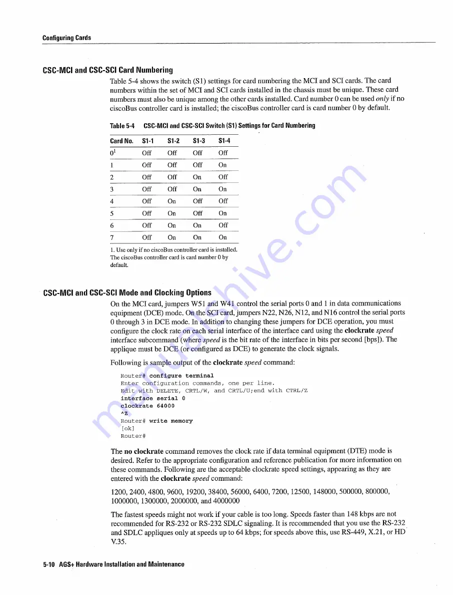
Table
5-4
shows
the switch
Si
settings
for card
numbering
the
MCI
and
SCI
cards
The
card
numbers
within
the
set
of
MCI
and SCI
cards
installed
in
the chassis
must
be
unique These
card
numbers must
also
be
unique
among
the
other cards installed
Card number
can be used
only
if
no
ciscoBus
controller card
is
installed
the
ciscoBus
controller card
is
card
number
by
default
Table
5-4
CSC-MCI
and CSC-SCI
Switch
Si
Settings
for
Card Numbering
Card
No
Si-i
S1-2
S1-3
Si-4
01
0ff
Off
Off
Off
Off
Off
Off
On
Off
Off
On
Off
Off
Off
On
On
Off
On
Off
Off
Off
On
Off
On
Off
On
On
Off
Off
On
On
On
Use
only
if
no ciscoBus
controller
card
is
installed
The
ciscoBus
controller
card
is
card
number
by
default
CSC-MCI
and CSC-SCI
Mode
and Clocking Options
On
the
MCI
card jumpers
W5
and
W4
control
the
serial
ports
and
in
data
communications
equipment
DCE
mode On
the
SCI card jumpers
N22 N26 N12
and
N16
control the
serial
ports
through
in
DCE
mode
In addition
to
changing
these
jumpers
for
DCE
operation
you must
configure
the
clock
rate
on
each
serial
interface
of the
interface
card using
the
clockrate
speed
interface
subcommand
where
speed
is
the
bit rate
of
the
interface
in bits
per second
The
applique
must be
DCE
or
configured
as
DCE
to
generate
the
clock
signals
Following
is
sample
output of
the
clockrate
speed
command
Router
configure
terminal
Enter configuration
commands
one
per
line
Edit
with DELETE
CRTL/W
and
CRTL/U
with CTRL/Z
interface
serial
clockrate
64000
AZ
Router
write memory
Router
The no
clockrate
command
removes
the
clock
rate if
data terminal
equipment
DTE
mode
is
desired
Refer
to
the appropriate configuration
and reference publication
for
more
information
on
these
commands
Following
are the acceptable
clockrate
speed
settings
appearing
as
they are
entered
with the clockrate
speed
command
1200
2400 4800 9600
19200
38400
56000 6400 7200
12500
148000
500000
800000
1000000
1300000
2000000
and 4000000
The
fastest
speeds
might
not
work
if
your cable
is
too
long Speeds
faster
than 148
kbps
are not
recommended
for
RS-232
or
RS-232
SDLC
signaling
It
is
recommended
that
you
use
the
RS-232
and
SDLC
appliques
only
at
speeds
up
to
64kbps
for speeds
above
this use
RS-449 X.21
or
HD
V.35
5-10
AGS
Hardware
Installation
and Maintenance
Summary of Contents for AGS+
Page 1: ...CISCO SYSTEMS ...
Page 11: ...AGS Hardware Installation and Maintenance ...
Page 17: ...Document Conventions xvi AGS Hardware Installation and Maintenance ...
Page 27: ...Chassis Power Budget 1 10 AGS Hardware Installation and Maintenance ...
Page 39: ...Chassis Components 2 12 AGS Hardware Installation and Maintenance ...
Page 57: ...System Bootstrap Diagnostics 4 10 AGS Hardware Installation and Maintenance ...
Page 83: ...Card Illustrations 5 26 AGS Hardware Installation and Maintenance ...
Page 105: ...FOOl Optical Bypass Switch Pinout A 22 AGS Hardware Installation and Maintenance ...
Page 121: ...Applique LED Indicators B lB AGS Hardware Installation and Maintenance ...
Page 125: ...C 4 ACS Hardware Installation and Maintenance ...
Page 127: ...Compliance Provisions D 2 AGS Hardware Installation and Maintenance ...
Page 129: ...E 2 AGS Hardware Installation and Maintenance ...


