background image

77

Instruction Manual

AFQm

Table 33 (Cont�): Modbus memory map: Filter messages (Table 2)�

Bit

Description

0x00100000

Contactor faults

0x00200000

Temperature Inductor 2 alarm

Table 34:Modbus memory map: Filter messages (Table 3)�

Parameter

Address

Initial Conditions for which the device does not start up. 

(5)

108

Bit

Description

0x0001

Discharging DC bus

0x0002

Minimum Mains Voltage

0x0004

Minimum temperature value

0x0008

Frequency error

0x0010

Charging DC bus

0x0020

Minimum DC bus voltage

0x0040

DC Bus imbalance

0x0080

The device does not communicate

0x0100

Polarity Error

0x0200

Minimum load current

0x0400

Maximum charge current

(5)


For a system with devices in parallel, the parameter value is that of the device connected with RS-485.

Table 35:Modbus memory map: Filter messages (Table 4)�

Parameter

Address

AFQm

 status 

(6)

104

Status (Decimal value)

Description

0

Start-up

10, 20, 30

Calibration

40

Relay test

50

Expect communications

60

Configuration

100

Start

200

Initial conditions

300

Stop

400

Synchronising

500

DC bus load

600

Operation

666

Power off

700

Alarm

(6) 


For a system with devices in parallel, the parameter value is that of the device connected with RS-485.

Summary of Contents for AFQm Series

Page 1: ...INSTRUCTION MANUAL Active Parallel Multi Function Filter AFQm M217B01 03 19B...

Page 2: ...2 AFQm Instruction Manual...

Page 3: ...prior to connecting the unit Follow all installation and maintenance instructions throughout the unit s working life Pay special attention to the installation stan dards of the National Electrical Co...

Page 4: ...CONNECTION AND CURRENT MEASUREMENT ON THE LOAD SIDE 28 3 7 3 3 WIRE CONNECTION AND CURRENT MEASUREMENT ON THE MAINS SIDE 29 3 7 4 3 WIRE CONNECTION AND CURRENT MEASUREMENT ON THE LOAD SIDE 30 3 7 5 3...

Page 5: ...URATION 66 7 8 ALARMS 68 7 9 ETHERNET COMMUNICATIONS 69 7 10 RS 485 COMMUNICATIONS 69 7 11 DATE TIME 70 7 12 SAVE DATA 71 8 RS 485 COMMUNICATIONS 72 8 1 CONNECTIONS 72 8 2 PROTOCOL 73 8 2 1 EXAMPLE OF...

Page 6: ...04 19 M217B01 03 19B Change in the following sections 11 Note The images of the devices are for illustrative purposes only and may differ from the original device SYMBOLS Table 2 Symbols Symbol Descr...

Page 7: ...any problem is noticed upon reception immediately contact the transport company and or CIRCUTOR s after sales service 1 2 TRANSPORT AND HANDLING The transport loading and unloading and handling of th...

Page 8: ...le that supports the device Figure 2 There might be an offset in the centre of gravity from the centre of the cabinet as a result of the uneven distribution of loads inside the device The neces sary p...

Page 9: ...uneven surfaces Do not store them in outdoor areas humid areas or areas exposed to splashing wa ter Avoid hot spots maximum ambient temperature 50 C Avoid salty and corrosive environments Avoid stori...

Page 10: ...filters The device features 3 4 wire multifunction for installation in three phase mains with or without neutral Parallel installation of up to 100 devices EMI filters LCD touch display to view the p...

Page 11: ...tion for installation in three phase mains with or without neutral Parallel installation of up to 100 devices LCD touch display to view the parameters RS 485 and Ethernet communications EMI filters En...

Page 12: ...in three phase mains with or without neutral Parallel installation of up to 50 devices Model 200A 30 devices Model 300A and 25 devices Model 400A LCD touch display to view the parameters RS 485 and Et...

Page 13: ...cause serious damage to the device itself and to other devices of the installation Only suitable for assembly on concrete or other non combustible surfaces and in restricted access areas The devices a...

Page 14: ...he maximum power of the device according to the internal temperature to ensure the best perfor mance in any condition Table 7 Ventilation distances Wall type AFQm Ventilation distances Wall type AFQm...

Page 15: ...FEATURES Table 8 Ventilation distances Rack type AFQm Ventilation distances Rack type AFQm 300 mm 300 mm 3 2 1 3 Cabinet type AFQm The cabinet type AFQm uses a forced ventilation cooling system with...

Page 16: ...storage period Table 10 Start up process according to storage time Storage time Process 1 year No special treatment required 1 year Connect the AFQm to the mains at least one hour before starting up...

Page 17: ...cm You can install more than one AFQm in a single cabinet Follow these steps to install it inside the cabinet 1 Extend the rack cabinet s anti tip feet Unless the rack cabinet is secured to the floor...

Page 18: ...st never be welded to the floor using arc welding as this may destroy the electronic components The device s top panel is part of the ventilation system The top panel is inverted to make it easier to...

Page 19: ...protection devices Cabinet type AFQm models For the cabinet s power supply a cable with a cross section suitable for the max imum current that can flow through the device must be used Although the dev...

Page 20: ...standards Check that there is a neutral in the place where three phase active filter connections are made with neutral AFQm 4WF xxxx The active filter must be of the correct size for the harmonic cur...

Page 21: ...type AFQm model are located on the lower face of the device The device has a terminal cover on the mains connection terminals Figure 8 Terminal cover AFQm xxx 030M and AFQm xxx 060M Figure 9 Terminal...

Page 22: ...tions 17 N Mains connection N 8 S1 Current input L1 18 N Mains connection N 9 S2 Current input L1 19 Earth connection 10 S1 Current input L2 ETHERNET LINK IN OUT RS485 S1 S1 S1 S2 S2 S2 L1 L2 L3 1 3 4...

Page 23: ...T Output for parallel connection 14 L1 Mains connection L1 5 A RS 485 communications 15 L2 Mains connection L2 6 B RS 485 communications 16 L3 Mains connection L3 7 S RS 485 communications 17 N Mains...

Page 24: ...d never remove the cover closest to the front part Cabinets with connections at the top have a sheet in the upper part of the cabinet which can be machined as shown in Figure 15 to insert the connecti...

Page 25: ...with connections at the top Figure 16 Screws Once the front cover is open the device s terminals can be accessed Figure 17 Figure 18 and Figure 19 1 2 3 4 5 6 7 8 9 10 Figure 17 AFQm cabinet type ter...

Page 26: ...st of terminals Device terminals 1 S1 Current input L1 6 S2 Current input L3 2 S2 Current input L1 7 L1 Mains connection L1 3 S1 Current input L2 8 L2 Mains connection L2 4 S2 Current input L2 9 L3 Ma...

Page 27: ...N THE MAINS SIDE N L1 L2 L3 CARGA LOAD L1 L2 L3 RED MAINS S1 S2 S1 S2 S1 S2 L1 P1 P2 L2 L3 P1 P2P1 P2 S1 S2 P1 P2 S1 S2 P1 P2 S1 S2 P1 P2 N N Figure 20 Three phase measuring with 4 wire connection and...

Page 28: ...SIDE N L1 L2 L3 CARGA LOAD L1 L2 L3 RED MAINS S1 S2 S1 S2 S1 S2 L1 P1 P2 L2 L3 P1 P2P1 P2 S1 S2 P1 P2 S1 S2 P1 P2 S1 S2 P1 P2 N N Figure 21 Three phase measuring with 4 wire connection and current mea...

Page 29: ...CURRENT MEASUREMENT ON THE MAINS SIDE L1 L2 L3 CARGA LOAD L1 L2 L3 RED MAINS S1 S2 S1 S2 S1 S2 L1 P1 P2 L2 L3 P1 P2P1 P2 S1 S2 P1 P2 S1 S2 P1 P2 S1 S2 P1 P2 Figure 22 Three phase measuring with 3 wir...

Page 30: ...D CURRENT MEASUREMENT ON THE LOAD SIDE L1 L2 L3 CARGA LOAD L1 L2 L3 RED MAINS S1 S2 S1 S2 S1 S2 L1 P1 P2 L2 L3 P1 P2P1 P2 S1 S2 P1 P2 S1 S2 P1 P2 S1 S2 P1 P2 Figure 23 Three phase measuring with 3 wir...

Page 31: ...S1 S2 S1 S2 S1 S2 L1 P1 P2 L2 L3 P1 P2P1 P2 S1 S2 P1 P2 S1 S2 P1 P2 CARGA LOAD L1 L2 L3 RED MAINS Figure 24 Three phase measuring with a 3 wire connection and 2 current transformers on the mains side...

Page 32: ...S1 S2 S1 S2 S1 S2 L1 P1 P2 L2 L3 P1 P2P1 P2 S1 S2 P1 P2 S1 S2 P1 P2 CARGA LOAD L1 L2 L3 RED MAINS Figure 25 Three phase measuring with a 3 wire connection and 2 current transformers on the load side...

Page 33: ...to be connected to each device Master 1 2 100 Figure 26 Connection of 2 to 100 filters in parallel Transformers on the mains side Master 1 2 100 Figure 27 Connection of 2 to 100 filters in parallel Tr...

Page 34: ...1 connector Pinout 4 3 2 1 1 Not connected 2 CAN A 3 CAN B 4 Not connected Note The communication cable must be a CAT 5 cable or higher Connect the OUT terminal from the master filter to the IN termin...

Page 35: ...r cabinet to the IN terminal from the master device of the following cabinet and the OUT terminal from the final slave device in this cabinet to the IN terminal of the master device of the following c...

Page 36: ...c cable heating circuit breaker disconnection damage to sensitive devices etc Table 15 Frequency of each harmonic Order n Mains frequency Fundamental 50 Hz Fundamental 60 Hz 3 150 Hz 180 Hz 5 250 Hz 3...

Page 37: ...tal voltage or current and the corresponding fundamental value Harmonic distortion rate THD The ratio between the RMS value of the harmonic content of the voltage and or current and the value of the f...

Page 38: ...DS RED MAIN N S1 S2 P1 P2 IF IC IR AFQm Figure 31 General connection diagram of an active filter 4 2 OPERATING PRINCIPLE Active filters are based on the following principle IFILTER IMAINS ILOAD Equati...

Page 39: ...m a THD V under voltage of over 3 It has been seen that the higher the initial THD V the greater the chance of filter overload The reason for this behaviour is that the load does not behave as a curre...

Page 40: ...s ICNL producing the harmonics to be filtered Equation 6 Equation 6 Calculating the short circuit ratio RSC In a real installation the short circuit current ISC in the PCL can be assessed by having th...

Page 41: ...t THD The user will see that the current THD is worse when connecting the filter or that the filter does not correct the current THD as expected In addition the filter detects an increase in the curre...

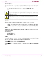
Page 42: ...last action To reactivate it just touch the display The last screen before entering the energy saving mode will be shown The display is divided into three areas Figure 36 246 246 Upper area Central ar...

Page 43: ...ARNINGS And the necessary keys at each point Table 17 Table 17 Central area keys Key Function Restarts the device after an alarm Starts the active filter Stops the active filter 4 6 3 LOWER AREA Figur...

Page 44: ...r master Use the key to navigate to the display screen of the load parameters 6 5 POWER AND COS OF LOAD and Make sure the active power measurement of the load corresponds to the active power levels of...

Page 45: ...e of filter power used The key allows you to restart the device if an alarm has been generated and this has been resolved The key is the start and stop key of the active filter Use the and keys to nav...

Page 46: ...escription Device stopped Alarm Description An alarm has been generated Access the Alarms screen 6 13 ALARMS to obtain more information 6 1 2 DEVICE SLAVE In Figure 41 the main screen of the slave dev...

Page 47: ...ch of the phases L1 L2 and L3 The current THD in the Mains in each of the phases L1 L2 and L3 The current THD in the Load in each of the phases L1 L2 and L3 Use the and keys to navigate through the di...

Page 48: ...te through the different display screens 6 4 POWER AND COS OF MAINS Note This screen is not visible on the slave devices Figure 44 shows the power and cos of the mains Figure 44 Display of the power a...

Page 49: ...ower S The cos Note The sign in reactive power indicates that it is capacitive and the sign that it is inductive Use the and keys to navigate through the different display screens 6 6 VOLTAGE HARMONIC...

Page 50: ...phases Figure 47 Display of the Mains harmonics Use the and keys to navigate through the different display screens 6 8 CURRENT HARMONICS LOAD Note This screen is not visible on the slave devices In th...

Page 51: ...s to select the separate display of each phase Use the and keys to navigate through the different display screens 6 10 WAVE SHAPE OF LOAD CURRENT Note This screen is not visible on the slave devices I...

Page 52: ...mains phasors are shown Figure 51 Mains phasors Use the and keys to navigate through the different display screens 6 12 LOAD PHASORS Note This screen is not visible on the slave devices In this screen...

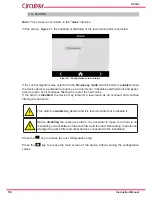
Page 53: ...en resolved Use the and keys to navigate through the different display screens Table 20 Alarm messages Alarm messages Overcurrent L1 L2 L3 Description The AFQm current is too high Corrective action Th...

Page 54: ...he configuration and the ambient temperature Check the quality of the power supply voltage If it persists contact the TAS Internal communications Description Failure in internal communications Correct...

Page 55: ...has passed since the last maintenance procedure was carried out and the maintenance meter was reset Corrective action Perform the annual maintenance procedure and reset the maintenance meter see 10 MA...

Page 56: ...necessary Low power factor Description The power factor value measured is less than 0 7 which might indicate a connection error in the measuring transformers where the voltage phases do not correspond...

Page 57: ...The temperature of the inductors and IGBTs can be high The AFQm is protected from these temperatures and they do not present any risk for the device Use the and keys to navigate through the different...

Page 58: ...ecessary to recalibrate it It is recommended to use a soft tip pointer take care not to damage the display and press icon The calibration screen is shown below Figure 59 Figure 59 Calibrate touch sens...

Page 59: ...e device status screen 1 The slave to be checked can be selected from the top tab by serial number Select the slave the screen shown in Figure 61 will be displayed This screen shows the Model Type and...

Page 60: ...essed in display mode i e all param eters of the device are shown but they cannot be modified By pressing the key the setup menu is accessed in edit mode i e the parame ters of the device can be modif...

Page 61: ...the next configuration step Press the key to access the main screen of the device without saving the configuration values 7 2 DEVICE SPECIFICATIONS Note This screen is informative it can not be modifi...

Page 62: ...the possible options are Single select this option if the AFQm does not have filters connected in parallel Master select this option if the filter is going to be used as the master of a group of devi...

Page 63: ...armonics to be neutralised from 3 to 25 TEMP Temporary Mode Harmonic filtering based on the instantaneous neutralisa tion of all harmonics Do not use Temporary mode if the supplier has not recommended...

Page 64: ...between phases and the reactive current com pensation is prioritised over the harmonic filtering With the function disabled priority is given to the current harmonic filtering and power factor correct...

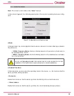
Page 65: ...red are selected in this screen Figure 68 Figure 68 Configuration screen Harmonic selection Press the key to access the next configuration step Press the key to access the main screen of the device wi...

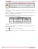
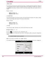
Page 66: ...active filter to be limited The value is config ured as a percentage with respect to the device s rated power Range of values Minimum value 20 Maximum value 100 Cos This parameter allows select the c...

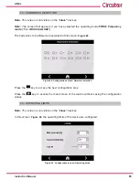
Page 67: ...ransformers is configured with this parameter the options are LOAD If the transformers are installed in the load area downstream from the AFQm MAINS If the transformers are installed in the mains area...

Page 68: ...it continues filtering the rest of the harmonics If the alarm is disabled the device may interpret a resonance as an overload and continue filtering the harmonic This option is enabled by default and...

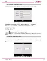
Page 69: ...rs must be configured manually IP Address IP address Netmask subnet mask Gateway gateway Press the key to access the next configuration step Press the key to access the main screen of the device witho...

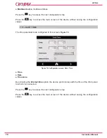
Page 70: ...7 11 DATE TIME The time parameters are configured in this screen Figure 74 Figure 74 Configuration screen Date Time Time Date Time zone By activating the Internet time option the device synchronises w...

Page 71: ...al AFQm 7 12 SAVE DATA The modified configuration values are saved in the final setup menu screen Figure 75 Figure 75 Final setup menu screen Press the key to save the modified data Press the key to e...

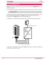
Page 72: ...cable with mesh shield minimum 3 wires with a maximum distance between the AFQm and the master device of 1200 metres A maximum of 32 AFQm filters can be connected to this bus To establish communicatio...

Page 73: ...0000 00FA xxxx Address 0A Responding peripheral number 10 in decimal Function 03 Read function No of bytes 04 No of bytes received Register 000000FA value of load current L1 with 1 decimal 0xFA 25 0...

Page 74: ...radians 9th order harmonic phase 158 165 172 0 001 x radians 11th order harmonic phase 159 166 173 0 001 x radians 13th order harmonic phase 15 A 167 174 0 001 x radians 15th order harmonic phase 15B...

Page 75: ...x radians 11th order harmonic phase 131 13E 14B 0 001 x radians 13th order harmonic phase 132 13F 14C 0 001 x radians 15th order harmonic phase 133 140 14D 0 001 x radians 17th order harmonic phase 1...

Page 76: ...10 Low 11 serial no DSP software version 10C HMI software version 1C3 3 For a system with devices in parallel the parameter value is that of the device connected with RS 485 8 2 2 4 AFQm filter messa...

Page 77: ...age 0x0040 DC Bus imbalance 0x0080 The device does not communicate 0x0100 Polarity Error 0x0200 Minimum load current 0x0400 Maximum charge current 5 For a system with devices in parallel the parameter...

Page 78: ...s 109 Bit Description Status 0x0001 Harmonic 3 1 Harmonic filtering 0 Harmonic disabled due to resonance 0x0002 Harmonic 5 0x0004 Harmonic 7 0x0008 Harmonic 9 0x0010 Harmonic 11 0x0020 Harmonic 13 0x0...

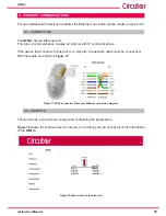
Page 79: ...with IP communications If the device that connects to this port is a computer the network cable must be a crossover Ethernet cable as shown in Figure 77 Figure 77 RJ 45 connector Crossover Ethernet co...

Page 80: ...e Administrator section There are two types of user 1 User with write access admin Table 37 Default username and password for a user with write access Default User and Password User name admin Passwor...

Page 81: ...ust be carried out Note The time intervals of the maintenance operations can vary depending on the device s operating conditions and environmental factors Follow the safety instructions in the SAFETY...

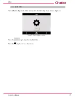
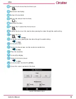
Page 82: ...atus and torque of the electrical connections as well as the mechanical attach ment to the wall 5 Reset the standard maintenance meter to do so Access the main setup screen Figure 79 Main configuratio...

Page 83: ...deteriorate The following symptoms in the filter behaviour could indicate a deterioration of the fans Increase in fan noise Increase in temperature of the device under the same environmental conditio...

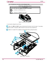
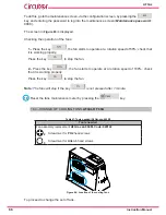
Page 84: ...or Allen 3 head screws Figure 81 Location of the cooling fans To proceed to change the set of fans 1 Place the AFQm in STOP mode and disconnect the device from the power If necessary disconnect all th...

Page 85: ...er Be careful when passing the cable through the wall bushing 10 Replace the fans 2 0 7 Nm 11 Fit the fan cover passing the fan cable through the wall bushing 1 5 Nm 12 Connect the fans 13 Tighten the...

Page 86: ...ly Press the key to stop the fan 2 Press the key the fan starts to operate at a rotation speed of 100 check that it is working properly Press the key to stop the fan Note The fans will stop if the key...

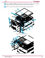
Page 87: ...ary disconnect all the connection cables and short circuit the current transformers 2 Wait for 1 minute for the capacitors to discharge before opening the device 11 8 5 3 3 6 11 4 Wall bushing Lower c...

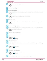
Page 88: ...s 2 10 Disconnect the upper floor fans 11 Remove the 16 screws from the lower fan cover and disassemble Run the fan cables from the upper level through the wall bushing 2 12 Disconnect the lower floor...

Page 89: ...RACK Table 42 Tools needed AFQm xxx 100R Tools needed Fan assembly replacement AFQm xxx 100x Code 920124 25 Screwdriver for Torx 25 head screws 4 Screwdriver for Allen 4 head screws 5 Screwdriver for...

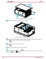
Page 90: ...ge of cooling fans Step 4 5 Remove the 4 screws from the board bracket and carefully disassemble the boards Re move the wall bushing from the fan cables to allow disassembly 4 6 Remove the screws from...

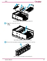
Page 91: ...ange of cooling fans Step 5 6 8 9 Remove the 3 screws from the fans 4 9 Figure 90 AFQm xxx 100R Change of cooling fans Step 9 10 Remove the fan assembly by pulling it up and replace it with the new fa...

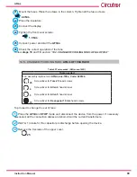
Page 92: ...d fans 17 Mount the top cover 4 5 Nm 18 Connect power and start the AFQm 19 Check the correct operation of the fans Follow steps 18 and 19 section 10 3 CHANGE OF COOLING FANS AFQm OF 30A 10 6 CHANGE O...

Page 93: ...or the capacitors to discharge before opening the device 3 Remove the 6 screws from the front cover 2 3 3 Figure 92 AFQm xxx 100M Change of cooling fans Step 3 4 Disconnect the display 4 Figure 93 AFQ...

Page 94: ...er for Allen 4 head screws 5 Screwdriver for Allen 5 head screws 10 Screwdriver for Hexagonal 10 mm head screws To proceed to change the set of fans 1 Place the AFQm in STOP mode and disconnect the de...

Page 95: ...Rated current phase Ina phase 100 A 200 A Rated current neutral Ina neutral 300 A 600 A Short time withstand current Icw 3 5 kA 1 second 3 5 kA 1 second Peak current Ipk 84 kA peak 84 kA peak Rated c...

Page 96: ...stable Parallel connection Up to 100 devices of different calibres Connection of the transformers only in the Master device AFQm 3WF 030M AFQm 3WF 060M AFQm 4WF 030M AFQm 4WF 060M Efficiency filter ha...

Page 97: ...10 Electromagnetic compatibility Installation in type A environments Standards Electromagnetic compatibility CEM Part 6 4 Generic standards Emis sions standard for industrial environments IEC 61000 6...

Page 98: ...Type Mains M6 ring terminal 12 mm 2 2 2 4 Nm PH2 Earth M6 ring terminal 16 mm 2 2 2 4 Nm PH2 Connections Type Current 6 pole connector max 2 5 mm2 0 5 0 6 Nm Flat 3 mm RS 485 3 pole connector max 2 5...

Page 99: ...M6 ring terminal 12 mm 2 2 2 4 Nm PH2 Earth M6 ring terminal 16 mm 2 2 2 4 Nm PH2 Connections Type Current 6 pole connector max 2 5 mm2 0 5 0 6 Nm Flat 3 mm RS 485 3 pole connector max 2 5 mm2 0 5 0...

Page 100: ...60 dBA Connections Type Mains M8 ring terminal 23 mm 8 10 Nm PH2 Earth M10 ring terminal 10 14 Nm Hex 17 mm Connections Type Current 6 pole connector max 2 5 mm2 0 5 0 6 Nm Flat 3 mm RS 485 3 pole co...

Page 101: ...0 dBA Connections Type Mains Ring terminal M8 23 mm 8 10 Nm PH2 Earth Ring terminal M10 10 14 Nm Hex 17 mm Connections Type Current 6 pole connector max 2 5 mm2 0 5 0 6 Nm Flat 3 mm RS 485 3 pole conn...

Page 102: ...J 45 Mains Filter Bar Drill Diameter of the Cable Screw Terminal width AFQm xxx 100C 30x3 1xM10 50 mm2 M10 8 8 32 mm 45 Nm AFQm xxx 200C 40x5 1xM10 50 mm2 M10 8 8 37 mm 45 Nm AFQm xxx 300C 40x10 1xM10...

Page 103: ...103 Instruction Manual AFQm 608 812 1755 665 465 1890 Figure 98 Dimensions Cabinet type AFQm...

Page 104: ...rom a pos sible failure improper installation or improper usage of the unit Consequently this guarantee does not apply to failures occurring in the following cases Overvoltages and or electrical distu...

Page 105: ...105 Instruction Manual AFQm 14 CE CERTIFICATE...

Page 106: ...106 AFQm Instruction Manual...

Page 107: ...107 Instruction Manual AFQm...

Page 108: ...CIRCUTOR SA Vial Sant Jordi s n 08232 Viladecavalls Barcelona Tel 34 93 745 29 00 Fax 34 93 745 29 14 www circutor com central circutor com...

Reviews: