23
and clicking calibrate to verify the component is now centered;
(4)
Save:
Saves the set offsets for the PCB calibration;
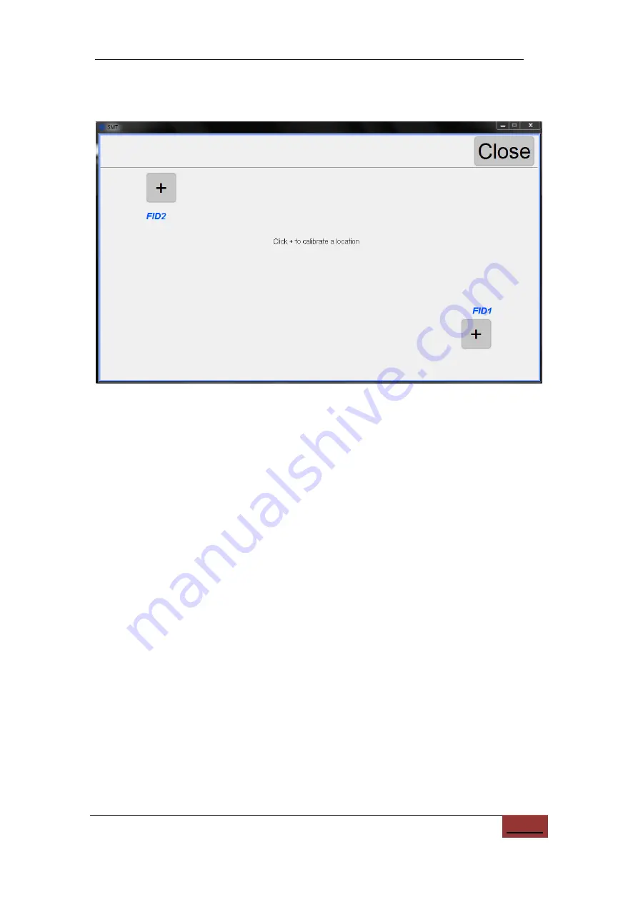
Figure
10.17.
Window for calibrating PCB points.
10.2. Load Work File
The load work window is used to run the machine and monitor its progress.
(1)
Current step:
Showing current component step and total number, click to set the
component step which will mount next;
(2)
PCB ID:
For batch mode, show current PCB ID number and total. Click to set
current PCB number, which will mount next;
(3)
Place count.:
Show total count of placed components;
(4)
PCB count:
For batch mode, show total count of PCB boards;
(5)
Average speed:
Show average mounting speed, in chips per hour;
(6)
Elapsed time.:
Run time;
(7)
Adjust Tray Start:
When feeders are defined in the IC tray, this button appears.
Click to set the start IC number;
(8)
Up camera (bottom left):
Click to watch image of up camera;
(9)
Down Light (2
nd
left):
Click to toggle light on and off;
(10)
PCB calibrate (3
rd
left):
Click to calibrate the PCB position;
(11)
Vacuum checks (4
th
left):
Click to toggle on and off the vacuum checks;
(12)
Head to Home (5
th
left):
Click to send head to home position, at back-right
;


