14
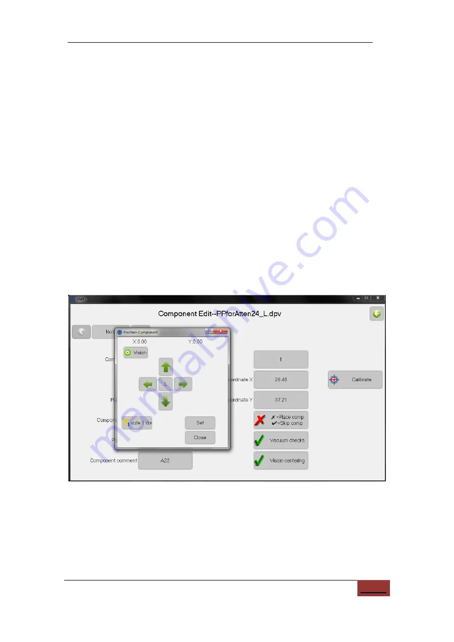
Additional commands for the two modes are:
(6)
Vision mode:
The center of the down-camera image is moved to the component
coordinate. The image is displayed on the right. Move the image until the
crosshairs are centered on the component.
i.
Enlarge:
Toggles between a normal and zoomed-in image;
ii.
Find Target:
Locates the component center automatically. The algorithm
searches from the image center outward, and the first closed graph is
identified as the target and marked with a red rectangle. This target, typically
a silk-screen pattern, must image cleanly and be closed. Positioning with the
silk screen is not always accurate, so the alignment should also be checked
manually with the footprint.
iii.
Auto Center:
Move to the center of target if target was captured;
(7)
Nozzle mode:
The selected nozzle is placed at the component coordinate. No
image is shown.
i.
Nozzle 1\2 down:
When pressing this button, the nozzle moves down to the
PCB. This is used for manual alignment of the nozzle to the pad;
Figure 10.5.
Visual alignment for nozzle.
10.1.2.
Feeder
User information for setting up a job is typically entered in the feeder tab, which
defines what feeders the parts come from. The screen shown below is used to manage


