17
window to align the feeder system. Details in next section;
(15)
Pick offsets used:
Text in red, when option chosen in set parameters window.
10.1.2.1. Feeder Calibrate
The feeder alignment must be checked every job since the tape is installed by hand
and the tape holes must be in the correct location for the needle pull operation. After
clicking align feeder, the head moves to the chosen feeder and an image is displayed from
the down camera.
Vision mode:
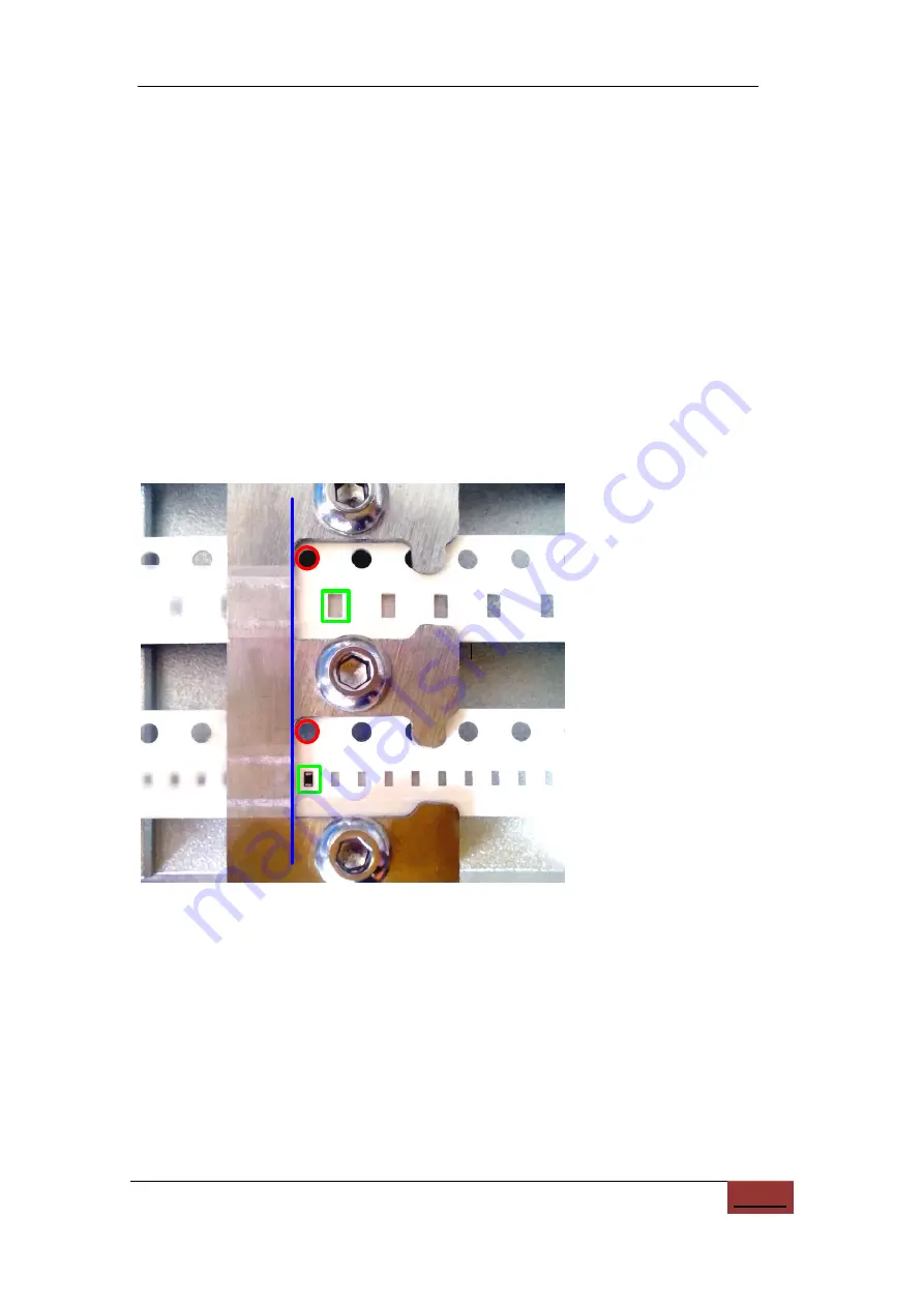
First, use the camera image to align, by hand, the tape hole (red circle)
against the feeder edge (blue line), as shown below. This gives an initial alignment of the
pull needle to the pull hole, which is good enough for a tape pull.
Figure
10.8.
Image from down camera to align feeders.
Nozzle mode:
By clicking the
“Nozzle” button, the image will disappear and the
nozzle will be centered over the component.
Click the “pull needle” icon just below the Y
coordinate to move the needle to the hole, lower the needle, and advance the, tape for a
distance given by feeder advance parameter. This checks the advance operation and
afterwards gives a more accurate machine alignment of the pull needle to the pull hole.


