8 Technical indicators and testing methods
8.5 Performance characteristics test
118
The local oscillation re-radiation is a measure of the ability of the device to be tested to suppress the
level of internal leakage from various local oscillation sources to the RF input port. Through the signal /
spectrum analyzer test to be tested device RF input port radiation signal maximum, that is, the local
oscillation re-radiation value.
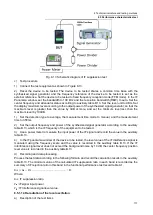
b) Test diagram and test instruments and equipment
Signal/Spectrum Analyzer .......................................................... Recommended FSVR/4051
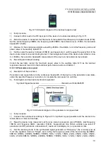
Fig. 8.14 Schematic diagram of the local oscillation re-radiation test
c) Test procedure
1) Connect the test equipment as in Fig. 8.14, the RF output of the device to be tested is connected to
the input of the signal/spectrum analyzer, and the device to be tested shares a common time base with
the signal/spectrum analyzer.
2) Reset the device to be tested. Set the frequency reference of the device to be tested as the external
reference. Set the scan mode to fixed frequency scan (FFM). Set the center frequency and attenuator
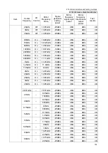
status according to auxiliary table B.14.
3) Set the center frequency of the signal/spectrum analyzer according to the auxiliary table B.14. Set
the bandwidth so that the resolution bandwidth is less than or equal to 10 kHz. Set the reference level
-30dBm and display the dynamic range 100dB. Set preamplifier on, track average, and average times 8
times.
4) On the signal/spectrum analyzer, the center frequency position leakage signal power is measured
using the frequency scale function and recorded in the auxiliary Table B.14. If the leakage signal is
smaller than the background noise, the noise power is recorded in the auxiliary table B.14.
d) Test record and data processing
Record the maximum value of the leakage signal power in the functional performance test record table
A.1.
8.5.1.15 Residual response
a) Description of the test items
The RF input port of the device to be tested is connected to a 50
load to examine the frequency
response of the device to be tested in the absence of signal input.
b) Test diagram and test instruments and equipment
50
load
3.5(f)-N type (m) connectors


