8 Technical indicators and testing methods
8.5 Performance characteristics test
112
3dB, and set the lowest level less than the highest level by 100dB.
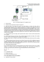
3) Set the measurement time of the device to be measured manually, 350ms, and set the detection
type to average.
4) Set the frequency of synthesized signal generator 1 and synthesized signal generator 2 according
to auxiliary table B.9, adjust the power of the two synthesized signal generators so that they arrive at the
input port of the equipment to be tested with equal power and equal to the table power value, allowing
the magnitude error ±0.5dB.
5) The level difference between the third-order intermodulation products on both sides and the input
signal is measured using the difference
frequency scale, and the absolute value of the difference (α) is
recorded in the auxiliary table B.9.
d) Recording and data processing
Calculate the third-order intercept points according to the following formula, and record the smaller value
of each test frequency point calculation in the auxiliary table B.9. The calculated IP
3
values are
summarized as the corresponding band third-order intercept point values and recorded in the functional
performance test record table A.1.
IP
3
=P
in
+α⁄2 ............................................
(
4
)
Where:
IP
3
- third-order intercept point value
;
P
in
- the input signal level value;
α - the absolute value of the level difference between the third-order intermodulation product and the
input signal.
8.5.1.10 Second-order intercept points
a) Description of the test items
The second-order intercept point (IP
2
) is a measure of the ability of the device under test to suppress
intermodulation interference signals generated at the receiving front-end at frequencies f
1
+f
2
and f
1
-f
2
by
two strong input signals with frequencies f
1
=f⁄2+∆f and f
2
=f⁄2-∆f, expressed as IP
2
=P
in
+α, where 2∆f is
the frequency interval of the two input signals; IP
2
is the third-order intercept point value, expressed in
dBm as a unit; P
in
is the
input signal level of the device to be measured, expressed in dBm; α is the
difference between the input signal level of the device to be measured and the level of the third-order
intermodulation product, that is, α=P
in
-P
t
, expressed in dB, where P
t
is the level of the third-order
intermodulation product, expressed in dBm as a unit.
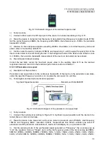
b) Test diagram and test instruments and equipment
Synthetic Signal Generator1..................................... Recommend 1464/E8257D
Synthetic Signal Generator2..................................... Recommend 1464/E8257D
Directional Coupler .......................................... Recommended AV70604
Directional Coupler .......................................... Recommended AV70607


