Appendix B: Troubleshooting Motion and Encoder Issues
Symptom or Error
Encoders don't count/
1. Are the encoders mapped correctly?
DRO doesn't update
GPIO4D systems running in velocity mode that do not utilize the
OpticDirect interface boards should have the encoders connected to the
MPU11 on encoder inputs 1-4 and should be mapped in the parameters
section as follows: 308 = 1, 309 = 2, 310 = 3, 311 = 4
NOTE: Although your mapping may differ, for troubleshooting
purposes, the default encoder mapping is described.
After confirming that the encoders are mapped as described above,
power the system completely off and then restart.
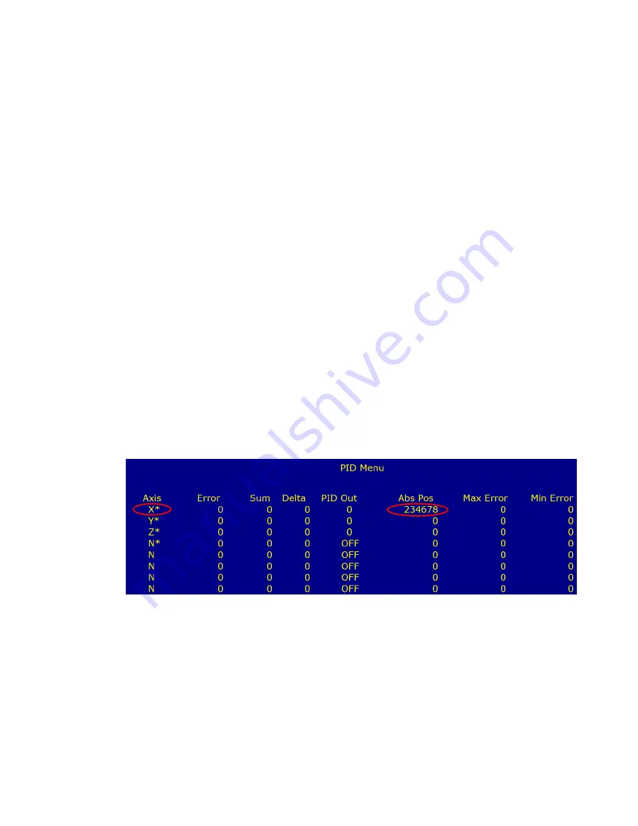
When CNC11 has restarted, enter the PID screen to view the Abs Pos
fields for each axis. To enter the PID screen from the main screen press:
F1
-Setup
→
F3 Config, password = 137, Press enter
→
F4 PID
The Abs Pos fields display the raw encoder counts for each axis. With
Estop pushed in, rotate the axis motor in question by hand while
observing the ABS Pos field for that axis and confirm that it counts
smoothly both more negative and more positive while rotating the motor
shaft CW and CCW. In the example below, testing is being done on the
X axis. Note that the Abs Pos field for the X axis is updating while the
motor shaft is rotated. If the Abs Pos field for the X axis does not update,
it would indicate an encoder or wiring issue. If any Abs Pos field other
than that of the X axis was updating, it would indicate that the encoder is
plugged into the wrong encoder input or is mapped incorrectly.
If you have and encoder that is working, plug it into the encoder input
that is being used for the encoder that is not counting to confirm that the
encoder input on the MPU11 is working correctly.


