12. Encoder wiring
3. Determining the number of encoder counts per motor revolution.
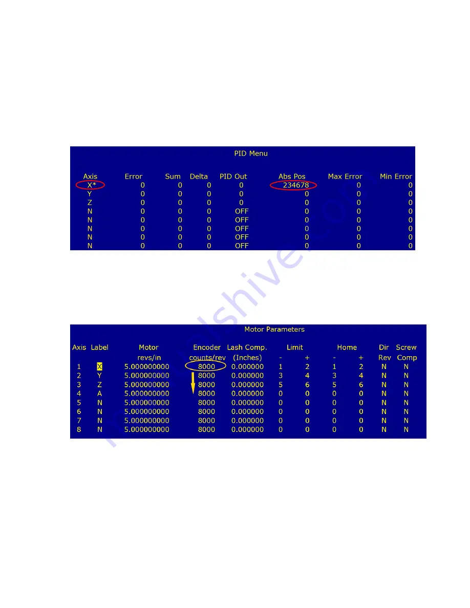
For each axis, rotate the motor until the asterisk appears next to the axis label as shown in
the below. Note the value of “Abs Pos”, rotate the motor shaft exactly 1 revolution until the
asterisk appears next to the axis label again and note the new ABS Pos. Subtract the two
and write down this value. This is the number of encoder counts per revolution of the motor.
If encoders don't count, check parameters 308-311 which should be set to 1, 2, 3, and 4
respectively. If you don't remember how to get to the parameter screen, review section 6.1
or see the Operators Manual.
4. Enter the number of encoder counts/rev in motor configuration.
Enter the encoder counts/rev as calculated above for each axis in the motor configuration
screen. From the main screen press:
F1-Setup
→
F3-Config, pw= 137, Press enter
→
F2 Mach-->F2->Motor
5. Enable Encoder faults
Go back into the parameter screen and change parameters 332-
335 back to 0. Press F10 to save. If you don't remember how to get to the parameter
screen, review section 6.1 or see the Operators Manual. If you see any differential or
quadrature errors, double check your wiring and make sure your shields are connected. A
properly wired encoder, using shielded, twisted pair cabling will not generate any faults.


