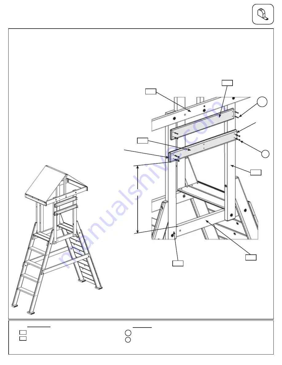
Step 46: A Frame Access Wall Assembly
A:
Measure 22-5/8” up from top of (391) A Frame Floor Support on A Frame Access Wall and attach (460)
Tunnel Left End flush to the outside edge of each (390) A Frame Upright with 4 (S7) #12 x 2” Wood Screws.
(fig 46.1 and 46.2)
B:
Centred between (460) Tunnel Left End and (392) A Frame Top Side attach (166) Wall Board to each (390)
A Frame Upright with 4 (S20) #8 x 1-3/8” Wood Screws. (fig. 46.1 and 46.2)
Fig. 46.1
x 4
392
166
460
22-5/8”
390
x 4
390
391
Hardware
4 x #8 x 1-3/8” Wood Screw
4 x #12 x 2” Pan Screw
Wood Parts
1 x
Tunnel Left End FSC 5/4 x 4 x 27-1/2”
1 x
Wall Board FSC 1 x 4 x 26-1/2”
460
166
A Frame
Access Wall
Note: (460) Tunnel Left
End must be flush to the
outside edge of each
(390) A Frame Upright.
DO NOT OVER HANG.
S7
S7
Flush
Flush
Fig. 46.2
S20
S20
121


