Q:
Tighten all 5 bolts from Step 51, Part 3 and 4.
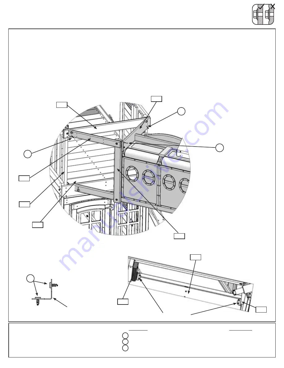
R:
Attach (510) Tunnel Right End to (160) Crowsnest Top with 1 (S15) #8 x 1-3/4” Wood Screw and to (511)
Tunnel Post with 1 (S7) #12 x 2” Pan Screw. (fig. 51.13)
S:
Attach (512) Tunnel Rail to (160) Crowsnest Top with 1 (S15) #8 x 1-3/4” Wood Screw. (fig. 51.13)
T:
Secure (513) Tunnel Corner Support and (161) Crowsnest Post to (153) Floor A with 1 Corner Brace per
board using 3 (S13) #6 x 5/8” Pan Screws per brace. (fig. 51.14 and 51.15)
Step 51: Attach Tunnel Assembly to Fort
Part 7
2 x
#8 x 1-3/4” Wood Screw
1 x
#12 x 2” Pan Screw
6 x
#6 x 5/8” Pan Screw
S13
Hardware
513
Fig. 51.13
S13
Fig. 51.14
Fig. 51.15
S7
510
511
160
512
161
153
S7
Inside View
S15
S15
2 x Corner Brace
Other Parts
Corner Brace
Corner Brace
153
S15
161
x 3 per
brace
134


