Hardware
Wood Parts
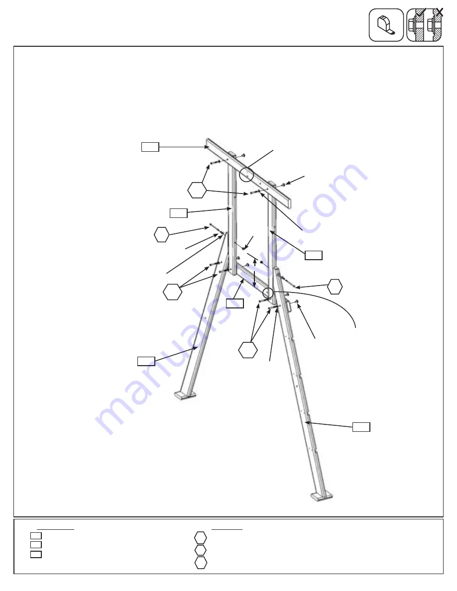
Step 40: A Frame Access Wall Assembly
Part 1
A:
Loosely attach 2 (390) A Frame Uprights to 1 (391) A Frame Floor Support with 2 (WB8) 5/16 x 2-3/8”
Wafer Bolts (with flat washer and t-nut) and to 1 (392) A Frame Top Side with 2 (WB9) 5/16 x 2-1/8” Wafer
Bolts (with flat washer and t-nut), as shown in fig. 40.1
.
B:
Loosely attach (381) A Frame Access L and 1 (382) A Frame Post to (391) A Frame Floor Support with 1
(WB8) 5/16 x 2-3/8” Wafer Bolt (with flat washer and t-nut) per board and to each (390) A Frame Upright with 1
(G22) 5/16 x 5” Hex Bolt (with lock washer, flat washer and t-nut) per board. (fig. 40.1)
Fig. 40.1
Notice bolt hole towards bottom
5/16” Flat
Washer
5/16” Lock
Washer
516”
T-Nut
5/16” Flat
Washer
5/16”
T-Nut
5/16” Flat
Washer
5/16”
T-Nut
4 x
5/16 x 2-3/8” Wafer Bolt (5/16” flat washer, 5/16” t-nut)
2 x
5/16 x 5” Hex Bolt (5/16” lock washer, 5/16” flat washer, 5/16” t-nut)
2 x
5/16 x 2-1/8” Wafer Bolt (5/16” flat washer, 5/16” t-nut)
2 x
A Frame Upright FSC 2 x 4 x 41-1/2”
1 x
A Frame Floor Support FSC 2 x 4 x 41”
1 x
A Frame Top Side FSC 5/4 x 4 x 49-3/4”
392
G22
390
G22
G22
392
391
391
381
382
390
390
WB9
WB8
WB9
WB8
WB8
11-3/8
”
Notice the distance between the
bottom of (391) A Frame Floor
Support and the bolt hole in
(390) A Frame Upright on both
boards must be 11-3/8”
Notice bolt hole
on this side
111


