background image

KGAET0201ETK: Installation Instructions

Manufacturer reserves the right to change, at any time, specifications and designs without notice and without obligations.

6

L12F018

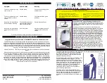
Fig. 4 – Location of Collector Box Vent Connection Trap Plug 

(Only used when Trap Kit is used on the Vent Pipe)

Venting and Combustion Air System Layout and 

Installation

NOTE: 

Slope  vent  pipes  a  minimum  of  1/4-in.  per  linear  ft.

(20mm/meter) toward the Vent/Exhaust Pipe External Trap Kit with no

sags between hangers. DO NOT slope the vent pipes toward the furnace

when using the trap kit on the vent/exhaust piping system. 

NOTE: 

Slope the combustion-air inlet pipes a minimum of 1/4-in. per

linear ft. (20mm/meter)  toward the exterior of the structure or insert a

second Trap Kit at the lowest point of the combustion-air inlet piping

system, within 24-in. (0.6 M) of the furnace.

B

ï

PLUG


THESE


PORTS

A

ï

OPEN

UPFLOW


ORIENTATION

B

ï

PLUG


THESE


PORTS

A

ï

OPEN

DOWNFLOW


ORIENTATION

B

ï

PLUG


THESE


PORTS

A

ï

OPEN

HORIZONTAL


RIGHT


ORIENTATION

A

ï

OPEN

B

ï

PLUG


THESE


PORTS

HORIZONTAL


LEFT


ORIENTATION

Representative drawing only, some models may vary in appearance

NOTE

:  

A. The lower

ï

most low

ï

side “pivot” port on the collector box is always left open for the internal drain trap.

B. Insert plugs into BOTH of the high

ï

side ports, ONLY when the Trap Kit is applied to the vent pipe.

C. DO NOT plug the trap port when the Trap Kit is used only for the combustion air pipe.

NOTICE

!

Follow all vent sizing and selection instructions that are included in the

Venting section of the furnace installation instructions.

The  Equivalent  Length  of  the  Vent/Exhaust  Pipe  External  Trap  Kit

should be assumed to be 15 feet (5 M) of straight length of PVC/ABS

DWV pipe.

CAUTION

!

UNIT OPERATIONAL HAZARD

Failure to follow this caution may result in intermittent unit operation.
This kit is intended to be located at the lowest point in the vent system

and no more than 24-in. (0.6M) horizontally from where the vent exits

the furnace to achieve proper drainage.

Summary of Contents for KGAET0201ETK

Page 1: ...r Follow the manufacturer s instructions in the use of primer and cement and never use primer or cement beyond its expiration date The safe operation as defined by ULC S636 of the vent system is based...

Page 2: ...rainage system and possibly the living space See Fig 3 Application to Combustion Air Inlet Piping Systems This Trap Kit may used to help prevent liquid moisture from the inlet piping system from enter...

Page 3: ...be either away from trap vent side or toward trap combustion air side curve of vent tee must be positioned toward termination toward major flow of condensate except as shown in Fig 2 i When larger di...

Page 4: ...t and transition to the pipe diameter required in the vertical portion of the pipe after the tee WARNING CARBON MONOXIDE POISONING HAZARD Failure to follow these warnings could result in personal inju...

Page 5: ...d listed to ULC S636 3 Not all materials below may be approved or listed to ULC S636 4 Royal Pipe and IPEX are approved suppliers of ULC S636 pipe fittings cements and primers 5 Factory accessory conc...

Page 6: ...PLUG THESE PORTS A OPEN DOWNFLOW ORIENTATION B PLUG THESE PORTS A OPEN HORIZONTAL RIGHT ORIENTATION A OPEN B PLUG THESE PORTS HORIZONTAL LEFT ORIENTATION Representative drawing only some models may va...

Page 7: ...llations must comply with regulations of local building heating plumbing or other codes in effect in area where installation is made Complete the installation of the drainage system as follows 1 Dry f...

Page 8: ...te 7 Listen for gurgling noises in the venting and drainage systems This is an indication that there are dips in the piping system or that the traps are not operating properly Correct the conditions a...

Page 9: ...g doors and windows and all doors between the space in which the appliance s connected to the venting system are located and other spaces of the building 4 Close fireplace dampers 5 Turn on clothes dr...

Page 10: ...y in appearance H G SLOPE UP TO TERMINATION 1 4 IN PER FOOT Two inch pipe shown When another size pipe is used discard the 2 in tee in the kit and use a field supplied tee that is the same diameter as...

Page 11: ...ISTS G B A AIR FLOW H SLOPE UP TO TERMINATION 1 4 IN PER FOOT Two inch pipe shown When another size pipe is used discard the 2 in tee in the kit and use a field supplied tee that is the same diameter...

Page 12: ...PIPIING See NOTES in Figure 1 COMBUSTION AIR INLET PIPE MAY TERMINATE IN WELL VENTILATED CRAWL SPACE VENTILATED COMBUSTION AIR OR EXTERNAL TO STRUC TURE TRAP KIT MAY ALSO BE APPLIED SLOPE UP TO TERMIN...

Page 13: ...rnace L12F029 Fig 12 Combustion Air and Vent Pipe Diameter Transition Location and Elbow Configuration Representative drawing only some models may vary in appearance TO CODE APPROVED DRAIN OR CONDENSA...

Page 14: ...rrier Company Edition Date 04 20 Catalog No AG KGAET 06 Replaces AG KGBET 01 KGAET0201ETK Installation Instructions Manufacturer reserves the right to change at any time specifications and designs wit...

Reviews: