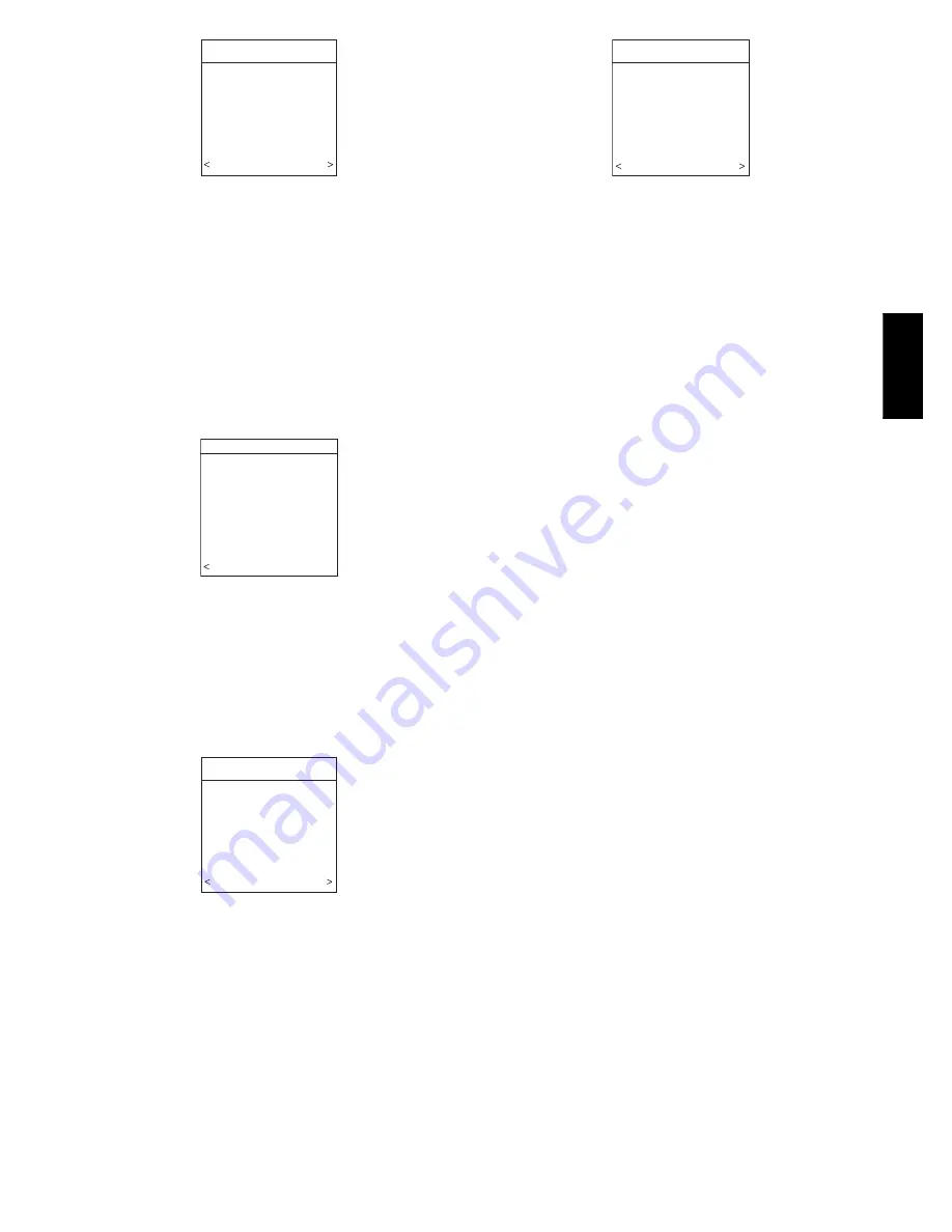
background image

9

INSTALL/SERVICE

EQUIPMENT SUMMARY

INSTALL

SETUP

CHECKOUT

SERVICE

SOFTWARE VERSION 1

  EXIT                 SELECT

A03200

Fig. 24 -- Install / Service Menus

NOTE

: The INSTALL / SERVICE menu will automatically exit

after 60 minutes of no push button activity.

EQUIPMENT SUMMARY:

Shows all equipment recognized by

and attached to the system.

INSTALL:

Used when adding, changing out, or un--installing

equipment.

SETUP:

Used to view or modify equipment settings.

CHECKOUT:

Allows testing of equipment operation

SERVICE:

Used to view operation and fault history of equipment

and enter dealer name/phone number for display

EQUIPMENT SUMMARY MENU

EQUIPMENT SUMMARY

FURNACE

58MVB0100-12

AC

24ANA136A003

FILTER

EAC

HUMIDIFIER

YES

UV LIGHTS

YES

ZONES

        1234

   BACK                       

A07117

Fig. 25 -- Equipment Summary

This screen shows indoor unit type and model number, outdoor

unit type (and model number if a 2--stage unit), filter type and any

accessories that are installed, and how many zones are recognized.

INSTALL MENU

This menu item will perform start--up process in order to learn all

equipment in system. Press right side button to initiate the process.
See Fig. 26.

INSTALL

TO ADD, UNINSTALL OR

RE-INSTALL EQUIPMENT,

PRESS RIGHT SIDE

BUTTON

   BACK               INSTALL

A03202

Fig. 26 -- Install Menu

SETUP MENU

This menu has several layers, allowing modification of equipment
settings. No settings will need to be made at equipment (i.e. DIP

switches on a furnace). All configuration settings made effective
from this menu will override equipment configuration made by dip

switches. Fig. 27 shows all the information that can be found in the

SETUP

menu.

SETUP

THERMOSTAT
FURNACE
HEAT PUMP
ZONING
ACCESSORIES
SYSTEM MAINTENANCE

   BACK               SELECT

A04089

Fig. 27 -- Setup Menu

Setup -- Thermostat

Auto Mode Setup:

S

Enable/Disable Auto Changeover mode (default = Enable).

S

Auto Changeover Time may be adjusted 5 to 120 minutes,
(default = 30 minutes).

When Auto mode is enabled (factory default) a change from heat

to cool (or vice versa) will not occur until an opposite mode
demand has existed for 30 minutes. If the setpoint is changed, the

30 minute timer is deleted.

Heat/Cool Deadband:

S

0 to 6

_

F (0 to 3

_

C), (default = 2

_

F).

The minimum difference enforced between heating and cooling
desired temperatures. This can allow one setting to “push” the

other to maintain this difference.

Offsets:

This option allows calibration (or deliberate miscalibration) of the
temperature and humidity sensors. These offsets are added to the

actual temperature/humidity values (default = 0).

S

Zone 1 Offset: --5 to +5

_

F (--3

_

C to +3

_

C).

S

Outside Temp Offset: --5 to +5

_

F (--3

_

C to +3

_

C).

S

Humidity Offset: --10 to +10%.

Elevation:

0 to 10000 feet. This value is used to correct the static pressure

readings the system performs.

Cycles Per Hour:

S

Maximum cycles per hour = 4 (default) or 6.

Programming:

S

ON (default)-- allows program schedule to be set by user.

S

OFF -- system becomes non--programmable

S

Periods Per Day = 2 or 4 (default = 4)

S

Programmable Fan On/Off (default = Off). If ON is selected, fan
can be set to Auto, Low, Med, or High.

Smart Recovery:

S

On or Off (default = On)

Applies to programmable operation only. Will start recovery 90

minutes prior to schedule change in both heating and cooling

mode. Refer to operational information for more detail.

English/Metric Display:

S _

F or

_

C (default =

_

F)

Reset Factory Defaults:
Program Schedule:

S

Yes/No to reset back to Energy Star default Time and Temp
schedules.

User Settings:

S

Yes/No to reset the user settings in the Advanced Setup to
factory default settings.

UIZ0

1

--

V

Summary of Contents for Infinity SYSTXCCUIZ01-B

Page 1: ...for personal injury Understand the signal words DANGER WARNING and CAUTION These words are used with the safety alert symbol DANGER identifies the most serious hazards which will result in severe pers...

Page 2: ...ne Control and Room Sensors should NOT be mounted S Close to a window on an outside wall or next to a door leading to the outside S Exposed to direct light or heat from a lamp sun fireplace or other t...

Page 3: ...ces shown in Fig 3 through 10 The User Interface will snap together with either the Recess Mount or the Surface Mount backplate Recess Mount This provides the thinnest mounting configuration See Fig 4...

Page 4: ...ative Backplate Recessed Mount Interlocking Tabs 4 Recessed terminal block in wall 11 2 38 1 mm wide by 21 8 54 mm high A07150 Fig 7 Recessed Mount Assembly Surface Mount Backplate to wall Interlockin...

Page 5: ...e dampers humidifier ventilator UV lights etc 12 Turn on power to equipment See wiring diagrams Fig 11 12 and 13 for connecting the Infinity Zone Control and Smart Sensors to the Damper Control Modul...

Page 6: ...speed indoor equipment furnace or fan coil cannot be found the User Interface will display CANNOT COMMUNICATE WITH INDOOR UNIT This MUST be corrected before the initial power up sequence can continue...

Page 7: ...hen press right side button to continue UV Lights Installed This screen will appear to select whether UV lights are installed on the system select YES or NO then press right side button to continue Zo...

Page 8: ...LEFT Up Down button 3 Press SCROLL button down to highlight MINUTE 4 Adjust the MINUTE setting using the LEFT Up Down button 5 Press SCROLL button down to highlight DAY 6 Adjust the current DAY setti...

Page 9: ...IES SYSTEM MAINTENANCE BACK SELECT A04089 Fig 27 Setup Menu Setup Thermostat Auto Mode Setup S Enable Disable Auto Changeover mode default Enable S Auto Changeover Time may be adjusted 5 to 120 minute...

Page 10: ...ehumidification airflow reduction This is nominally 350 CFM ton but will vary if a 2 stage outdoor unit is used S MAXIMUM 400 CFM ton Dehum Airflow S NORMAL factory default When equipment is running t...

Page 11: ...ry if a 2 stage outdoor unit is used S EFF 350 fixed airflow used to achieve specified ratings no dehumidification airflow reduction This is nominally 350 CFM ton but will vary if a 2 stage outdoor un...

Page 12: ...ff default Turns on Quiet Shift function in 1 stage or 2 stage communicating heat pumps High Cool Latch S OFF default S ON high cool stage on at all times unzoned only S 80 to 110_F 27 to 43_C unzoned...

Page 13: ...F DEFROST W WATER YES BLOWER OFF DELAY 30 SEC BACK A07031 Fig 31 Hydronic Heat Setup HOT WATER LOCKOUT Outside temperature above which the hot water will not operate except for defrost if selected S...

Page 14: ...ange to FURNACE CHECK and show the current operating status of the furnace Checkout Electric Heat S ELECTRIC HEAT RUNTIME 5 min Default time 5 min Range 0 120 min If you have a fan coil with electric...

Page 15: ...ximum amount of airflow to each zone Select ZONE then select AIRFLOW LIMIT When Start is pressed right side button the selected zone s damper will fully open all others will close and the indoor unit...

Page 16: ...tioner FN Furnace FC Fan Coil ZN1 Zone Board 1 ZN2 Zone Board 2 SPP Packaged product SAM System Access Module Service Run Fault History This information is stored in the equipment circuit boards if co...

Page 17: ...elected recovery time and gradually adjusts room temperature so desired temperature will be achieved at selected recovery time It operates in both heating and cooling This only applies to programmable...

Page 18: ...ed to overcool the space up to 3_F 6_C if the humidity level is above the cooling humidity target setpoint The amount of over cooling allowed varies with the dehumidification demand the cooling demand...

Page 19: ...e run mode How do I get back to start up 1 Press the ADVANCED button for at least 10 seconds 2 Install Service menu will appear 3 Scroll down to the INSTALL selection 4 Press the right side button the...

Page 20: ...mode the V model user interface will not transfer any settings or information to or from the regular user interface it only takes over control of the system After removing the V model user interface...

Reviews: