


16
Cubic Feet per Minute of air the User Interface is currently
requesting.
Blower RPM:
S
Actual blower motor RPM value
Static Press:
S
Inches of water. Displays the calculated static pressure the fan
coil is currently experiencing.
S
If static pressure cannot be accurately calculated, the display will
read UNKNOWN. When this is seen, the system is adjusting to
high static pressure by cutting back blower RPM.
Service -- Heat Pump / AC Status
Stage: (Heat / Cool)
S
OFF, LOW, HIGH
Displays stage of heating or cooling that the Heat Pump/AC is
delivering.
Defrost:
S
NO, YES
Displays status of defrost mode if heat pump.
Airflow CFM:
S
Airflow User Interface is requesting from blower.
Outdoor Coil Temp:
S _
F or
_
C (default =
_
F)
Temperature of the outdoor unit coil (only available on
communicating outdoor units).
Blower RPM:
S
Actual RPM feedback from indoor blower motor.
Static Press:
S
Calculated static pressure of indoor unit.
S
If static pressure cannot be accurately calculated, the display will
read UNKNOWN. When this is seen, the system is adjusting to
high static pressure by cutting back blower RPM.
Service -- Zoning Status
Zone Status:
This screen will show each zone in the system with the
corresponding damper position (POS), and CFM being delivered
to each zone. Damper position range is from 0 to 15 (0 = closed, 15
= open).
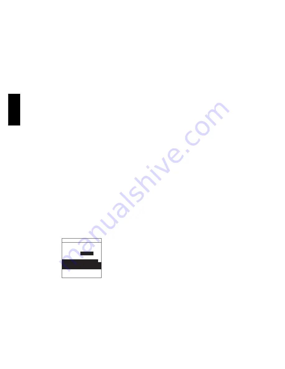
Service -- Last 10 System Events
LAST 10 EVENTS
LOW PRESSURE
3/2/05
2:35 PM
< BACK
MORE >
HP
3 EVENTS:
225 EVENTS _
ACTIVE
FN 2/28/05 6:10 PM
41-BLOWER MOTOR FAULT
F
SWITCH OPEN
F=FAULT
A07032
Fig. 35 -- Last 10 System Events
This screen will show last 10 events that occurred throughout the
system. Each entry has the time and date incident recorded. Service
technician should enter current date in “
TODAY’S DATE
”menu
section BEFORE checking and logging the last 10 system events.
These events are stored in the memory of the User Interface and are
resettable in the Thermostat Setup screen under the Reset Factory
Default selection.
Each entry has a two--letter acronym preceding the event name to
identify which piece of equipment generated the event. This event
history can be cleared under Thermostat Setup, Reset Factory
Defaults.
HP = Heat Pump
AC = Air Conditioner
FN = Furnace
FC = Fan Coil
ZN1 = Zone Board 1
ZN2 = Zone Board 2
SPP = Packaged product
SAM = System Access Module
Service -- Run / Fault History
This information is stored in the equipment circuit boards (if
communicating) and displayed on the User Interface. The indoor
unit and outdoor unit (if communicating) have the following
histories:
NOTE
: For Critical Fault Screens, see Troubleshooting section in
this document.
Resettable Faults:
S
Fault counters for each piece of equipment that can be reset.
Cycle Counters:
S
Number of heat/cool/power cycles the unit has performed.
Run Times:
S
Lifetime hours of operation in heating, cooling, and how long
the unit has been powered.
-- Kilowatt hours used of electric reheat for dehumidification.
Service -- Today’s Date
This menu item allows the installer to enter the current date. It is
used for time/date stamping of system faults. This should be
verified every time prior to viewing “LAST 10 SYSTEM
EVENTS” section.
Service -- Model / Serial Numbers
This menu item allows the installer to view the model number and
serial number (if available) of all communicating pieces of
equipment in the system. This information resides in the original
circuit board from the factory. If a circuit board has been replaced,
the model and serial number will no longer be displayed.
Service -- Service Phone Number
This menu item allows the installer to enter a name and phone
number that the homeowner can call for future service of the
system. This name and phone number will appear to the
homeowner whenever a service reminder pop--up message is
displayed (i.e. Change Filter, etc.).
To edit:
S
Use Right Up/Down button button to move cursor left and right.
S
Use Left Up/Down button button to select numbers and letters.
S
Use Scroll button to move up and down between NAME and
NUMBER.
OPERATIONAL INFORMATION
Zone Selection
S
Press top left ZONE button to select zones.
Continuous Fan Operation
Pressing FAN button will scroll through the following:
S
AUTO = No fan operation except during equipment operation.
S
LOW = Approximately 50% of High Speed operation.
S
MED = Half way between High and Low speed operation.
S
HIGH = Highest of either High Heating or High Cooling CFM.
Continuous fan operation is programmable. The programming
option must be enabled in the Thermostat Setup. See the
Homeowner’s Manual for detailed instructions on programming
the fan.
UIZ0
1
--
V


