


8
NOTE
: The static pressure check occurs only at initial installation,
or when INSTALL is run in the INSTALL/SERVICE menu.
Duct Assessment
The following screen will appear after STATIC PRESSURE screen
is exited. Press right--side button to start Duct Assessment. Duct
Assessment will measure the relative size of the ductwork, up
to
and through the dampers. These measurements are used to control
the correct amount of airflow in the zoned system. Status messages
will appear on the screen to indicate what the system is doing. The
process will take approximately one minute per zone. The duct
assessment will override a call for heat or cool.
A duct assessment will automatically occur each day at a user
selectable time. The factory default time is 1:00 p.m. but, may be
changed by entering the Zoning Setup menu. See Zoning Setup
section of this manual. The duct assessment will override a call for
heat or cool. The system will first open all zones and drive the
blower to 175 CFM/ton of cooling (or the minimum indoor unit’s
airflow, whichever is greater). It will then take a static pressure
measurement. The system will then close all zones and open one
zone at a time, taking a static pressure measurement for each zone.
The system will then close all zones and take a pressure
measurement, getting a value for the duct leakage up to and
through the dampers. With these static pressure measurements, the
system will calculate the relative size of each zone as well as the
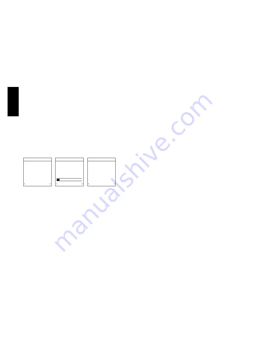
percent leakage through the dampers At the end of the process, the
display will show the relative size of each zone duct. See Fig. 23.
If the User Interface detects an error (damper not moving or
damper wired backwards), it will perform the duct assessment
again. If it still detects a damper problem, it will default the
measurements into equal sizes, with 10% leakage, and display the
zone number for the suspected zone damper.
DUCT ASSESSMENT
MEASURE DUCT
CAPACITY FOR EACH
ZONE.
4 MINUTES ARE REQUIRED
TO COMPLETE
PRESS START TO BEGIN
QUIT START
DUCT ASSESSMENT
ASSESSMENT ACTIVE
PLEASE WAIT
OPENING ALL ZONES
AIRFLOW STABILIZING
PROGRESS
STOP
DUCT ASSESSMENT
ZONE CAPACITY
ZONE1
25
ZONE 2
20
ZONE 3
25
ZONE 4
20
DAMPER LEAKAGE 10
QUIT START
A04085
Fig. 23 -- Duct Assessment
QUICK START
For first time installers, Quick Start will allow a quick start up of
the Infinity Zone System before learning all the details of system
operation. However, for the best possible comfort and operation
refer to the Infinity Zone Control Owner’s Manual.
Set Day, Time & Desired Humidity
1. Open the door of the Infinity Zone Control and press the
BASIC
button.
2. Adjust the highlighted
HOUR
setting using the
LEFT
Up/
Down button.
3. Press
SCROLL
button (down) to highlight
MINUTE
.
4. Adjust the
MINUTE
setting using the
LEFT
Up/Down
button.
5. Press
SCROLL
button (down) to highlight
DAY
.
6. Adjust the current
DAY
setting using the
LEFT
Up/Down
button.
7. Press
SCROLL
button (down) to highlight
HUMIDITY
.
8. Press the red
HEAT
button to select heating humidity.
9. Adjust desired heating humidity level using either (+/--) but-
ton.
10. Press the blue
COOL
button to select cooling humidity.
11. Adjust the desired cooling humidity level using ei-
ther(+/--)button.
12. To exit press
BASIC
button or close door.
13. If changes are made, you will be asked to “
SAVE
CHANGES? YES/NO
.”
Override Heating Schedule
1. Press the red
HEAT
button. Heating mode is confirmed
when the red LED next to the red
HEAT
button is lit.
2. Use the
RIGHT
Up/Down button to select your desired
heating temperature.
3. The default time for temporarily overriding the temperature
schedule is 2:00 HRS as indicated by the text on the lower
left.
NOTE
: Override time will not appear if programming has been
turned off.
4. You can change the temporary override time in 15--minute
increments by pressing the
LEFT
Up/Down button until
the desired override time is selected, or press the
HOLD
button anytime to override the schedule indefinitely.
Quick Program Schedule For All Days
This section will give you a quick program schedule for
ALL
DAYS
of the week. For more information on how to create
customized schedules for every day, the entire week, or weekend,
refer to the Owner’s Manual.
1. Open the door of the control.
2. Press the
SCHEDULE
button, which allows you to create
one schedule for the entire home.
3. Press either the
LEFT
or
RIGHT
side button repeatedly (if
necessary) until
“ALLDAYS”
is displayed. The
WAKE
time period will be highlighted.
4. Using the
LEFT
Up/Down button, set the start time for this
time period.
5. Press the red
HEAT
button. Heating temperature will begin
flashing.
6. Set the heating temperature using the
RIGHT
Up/Down
button.
7. Press the blue
COOL
button. Cooling temperature will be-
gin flashing.
8. Set the cooling temperature using the
RIGHT
Up/Down
button.
9. Set the remaining periods by using the
SCROLL
button to
select “
DAY
”, “
EVENING
”, and “
SLEEP
”.
10. To copy a zone, use
SCROLL
button to select
“COPY”
.
Select
YES
and copy this zone schedule to other zones us-
ing
NO
or
YES
.
11. Exit the scheduling mode by either closing the door or
pressing the
SCHEDULE
button.
12. If changes are made, you will be asked to “
SAVE
CHANGES YES/NO.
”
INSTALL / SERVICE MENUS
The
“INSTALL / SERVICE”
menus contain a set of vital
information. This information enables the Installer or Service
person to view a summary of what has been installed, etc. This
information is not covered in the Owner’s Manual.
To enter
INSTALL / SERVICE
menus, press and hold the
ADVANCED
button for at least ten seconds. The following menu
will appear (See Fig. 24):
UIZ0
1
--
V


