


2
Design Considerations
The Infinity Zone system is unique because a bypass damper must
not be used. This is possible due to the intelligence of the system
and variable speed motor technology. For trouble--free
applications, the following parameters should always be met:
1. Zones should be sized so that each zone can deliver at least
the minimum airflow for the system in both heating and
cooling modes.
2. Oversize duct work by 25% to avoid excess noise at mini-
mum zone airflow.
3. Be aware that heating airflow may be higher than cooling
airflow depending on equipment combination.
INSTALLATION, START--UP OVERVIEW
This instruction covers installation of the Infinity Zone Control
only
. Physical installation instructions for the indoor and outdoor
equipment, Damper Control Module, and accessories are provided
with each unit.
Setup, commissioning, operation, and troubleshooting of the
Infinity Zone System are covered in this installation instruction. It
is the guide to connecting the system components and
commissioning the system once all physical components are
installed. Special screen prompts and start--up capabilities are
provided in the Infinity System to simplify and automate the initial
commissioning of the system.
S
Install Infinity Zone Control according to this instruction.
S
Install indoor unit, outdoor unit, and accessories according to
their instructions.
S
Wire complete system according to this instruction.
S
Setup, commission, and operate system according to this
instruction to assure a smooth and trouble free start--up.
INSTALLATION
Check Equipment and Job Site
Inspect equipment. File claim with shipping company prior to
installation if shipment is damaged or incomplete.
Infinity Zone Control Location and Wiring
Considerations
ELECTRICAL OPERATION HAZARD
Failure to follow this warning could result in personal injury
or death.
Disconnect power before routing control wiring.
!
WARNING
All wiring must comply with national, local, and state codes.
Infinity Zone Control Location
The Infinity Zone Control User Interface is the command center for
the Infinity Zone System and is typically located in Zone 1 to sense
and control temperature in this zone. It should be located where it
is easily accessible and visible to the adult homeowner or end user.
For accurate temperature measurement, the following guidelines
should be followed:
The Infinity Zone Control and Room Sensors should be mounted:
S
Approximately 5--ft (1.5 meters) from the floor.
S
Close to or in a frequently used room, preferably on an inside
partitioning wall.
S
On a section of wall without pipes or ductwork.
The Infinity Zone Control and Room Sensors should
NOT
be
mounted:
S
Close to a window, on an outside wall, or next to a door leading
to the outside.
S
Exposed to direct light or heat from a lamp, sun, fireplace, or
other temperature--radiating objects which could cause a false
reading.
S
Close to or in direct airflow from supply registers.
S
In areas with poor air circulation, such as behind a door or in an
alcove.
Remote Room Sensor Option
A Remote Room Sensor can be used with the Infinity Zone
Control to take the place of the User Interface internal temperature
sensor. This allows the Infinity Zone Control to be mounted in
areas with less than optimal airflow (such as near an exterior door,
window or in a closet). The remote sensor can be wired to the
terminal block connectors labeled S1 and S2 at the User Interface
backplate, or the ZS1 and ZS1C connection at the Damper Control
Module. In either case, the Infinity Zone Control will automatically
detect the Remote Room Sensor and ignore its internal temperature
sensor. It is also important to note the humidity sensor cannot be
remotely located, so do not locate the Infinity Zone Control in an
area where humidity sensing may not be accurate.
In addition, the Remote Room Sensor is a temperature sensor only,
having no additional user inputs. This sensor is typically connected
to the Damper Control Module and used to sense and control
temperature in each zone.
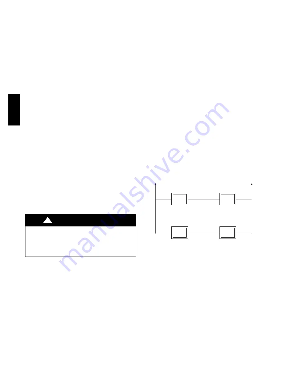
Remote Sensor Averaging
Typically, one Remote Room Sensor is used per zone, but multiple
sensors may be used and averaged in some applications. Averaging
requires a special series--parallel wiring method with a specific
number of sensors. See Fig. 2 in this manual for wiring diagram.
Sensor 1
Sensor 2
Sensor 3
Sensor 4
Damper Control
Module
ZS_
Damper Control
Module
ZS_C
A03233
Fig. 2 -- Remote Room Sensor -- Parallel Wiring
Smart Sensor
Any zone may use a Smart Sensor. It provides a temperature
display and buttons to adjust the desired temperature in that zone
only. It also displays outdoor temperature and indoor humidity
sensed at the User Interface. Only one Smart Sensor may be used
per zone. They cannot be averaged like Remote Room Sensors. If a
Smart Sensor is used in a zone, a Remote Room Sensor may also
be used in the same zone. The Remote Room Sensor has priority
over the Smart Sensor. The Smart Sensor will display the Remote
Room Sensor temperature.
NOTE
: Smart Sensors must be addressed to identify which zone it
will control. See Smart Sensor Installation Instructions for details.
Wiring Considerations
Ordinary thermostat wire is recommended. Use 22 AWG or larger
for normal wiring applications. Continuous wire lengths over
100--ft. (3 m) should use 20 AWG or larger.
NOTE
: ABCD bus wiring only requires a four--wire connection;
however, it is good practice to run thermostat cable having more
UIZ0
1
--
V


