


7
Equipment Summary
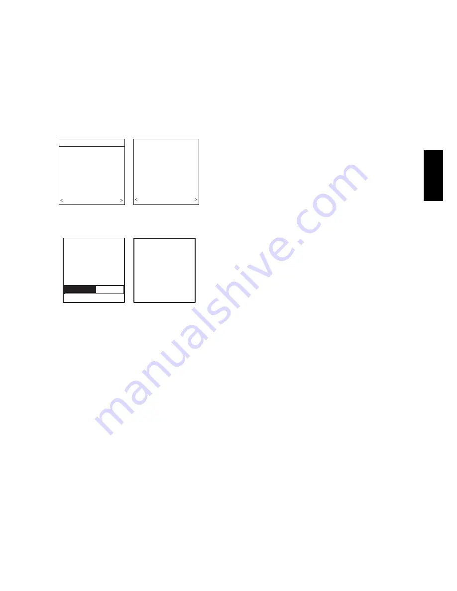
The “EQUIPMENT SUMMARY” screen will appear after
Accessories have been selected. This screen will give a summary of
all equipment automatically found or manually selected. If a wrong
selection was made, press left--side button (BACK selection) to go
back to that particular screen and make changes. When everything
is OK, press right--side button again to continue. (See Fig. 20.)
The “SETUP COMPLETE! SAVE ALL SELECTIONS?” screen
will appear after Equipment Summary. To Save All Selections
press (YES) right--side button. Pressing the left--side button (NO
selection) will return to the Equipment Summary screen where
changes can be performed to any of the equipment selection
screens. After selecting YES, the initial power up sequence of the
new Infinity Control is complete.
EQUIPMENT SUMMARY
FURNACE
58MVB0100-12
AC
24ANA136A003
FILTER
EAC
HUMIDIFIER
YES
UV LIGHTS
YES
NO YES
SETUP
COMPLETE!
SAVE
ALL SELECTIONS/
NO YES
A07247
Fig. 20 -- Equipment Summary
Static Pressure Check
STATIC
PRESSURE
CHECK
PLEASE WAIT
EXTERNAL STATIC
PRESSURE
MEASURED:
0.72 INCHES
AT 1200 CFM
CONTINUE >
A05000
Fig. 21 -- Static Pressure Check
This screen will appear after Setup is exited. The system will
perform a static pressure check. This process will take about 1 1/2
minutes to complete. When completed, a screen will appear
displaying the static pressure (in inches) across the equipment at
the expected highest delivered airflow. If the blower RPM is
greater than 1200, then a warning will appear, but equipment
operation and the TrueSense
t
dirty filter detection operation will
not be affected.
NOTE
: The static pressure check occurs only at initial installation,
or when INSTALL is run in the INSTALL/SERVICE menu.
QUICK START
For first time installers, Quick Start will allow a quick start up of
the Infinity System before learning all the details of system
operation. However, for the best possible comfort and operation
refer to the Infinity Control Owner’s Manual.
Set Day, Time & Desired Humidity
1. Open the door of the Infinity Control and press the
BASIC
button.
2. Adjust the highlighted
HOUR
setting using the
LEFT
Up/
Down button.
3. Press
SCROLL
button (down) to highlight
MINUTE
.
4. Adjust the
MINUTE
setting using the
LEFT
Up/Down
button.
5. Press
SCROLL
button (down) to highlight
DAY
.
6. Adjust the current
DAY
setting using the
LEFT
Up/Down
button.
7. Press
SCROLL
button (down) to highlight
HUMIDITY
.
8. Press the red
HEAT
button to select heating humidity.
9. Adjust desired heating humidity level using either (+/--) but-
ton.
10. Press the blue
COOL
button to select cooling humidity.
11. Adjust the desired cooling humidity level using ei-
ther(+/--)button.
12. To exit press
BASIC
button or close door.
13. If changes are made, you will be asked to “
SAVE
CHANGES? YES/NO
.”
Override Heating Schedule
1. Press the red
HEAT
button. Heating mode is confirmed
when the red LED next to the red
HEAT
button is lit.
2. Use the
RIGHT
Up/Down button to select your desired
heating temperature.
3. The default time for temporarily overriding the temperature
schedule is 2:00 HRS as indicated by the text on the lower
left.
NOTE
: Override time will not appear if programming has been
turned off.
4. You can change the temporary override time in 15--minute
increments by pressing the
LEFT
Up/Down button until
the desired override time is selected, or press the
HOLD
button anytime to override the schedule indefinitely.
Quick Program Schedule For All Days
This section will give you a quick program schedule for
ALL
DAYS
of the week. For more information on how to create
customized schedules for every day, the entire week, or weekend,
refer to the Owner’s Manual.
1. Open the door of the control.
2. Press the
SCHEDULE
button, which allows you to create
one schedule for the entire home.
3. Press either the
LEFT
or
RIGHT
side button repeatedly (if
necessary) until
“ALLDAYS”
is displayed. The
WAKE
time period will be highlighted.
4. Using the
LEFT
Up/Down button, set the start time for this
time period.
5. Press the red
HEAT
button. Heating temperature will begin
flashing.
6. Set the heating temperature using the
RIGHT
Up/Down
button.
7. Press the blue
COOL
button. Cooling temperature will be-
gin flashing.
8. Set the cooling temperature using the
RIGHT
Up/Down
button.
9. Set the remaining periods by using the
SCROLL
button to
select “
DAY
”, “
EVENING
”, and “
SLEEP
”.
10. Exit the scheduling mode by either closing the door or
pressing the
SCHEDULE
button.
11. If changes are made, you will be asked to “
SAVE
CHANGES YES/NO.
”
UID
01
--
V


