background image

27

Depending on the current operating type, the active setpoint 
can be selected:

•  By choosing the active setpoint in the General 

Parameters menu (Setpoint Select, GENUNIT).

•  Via the volt-free contacts (see section 3.7.3).
•  Via network commands [SP_SEL].
•  Via the schedule setting (schedule 2).

The following table summarises the possible setpoint selections 
based on the control type (local, remote, network) and the 
following parameters:

•  Heating/Cooling operating mode.
•  Setpoint select.
•  Setpoint selection contact status.
•  Schedule 2 status for setpoint selection [SP_OCC].

Parameters status

Active 

setpoint

Mode

SP_SEL 

(Local/Net)

Setpoint select  

(Local/Net)

Setpoint 

occupancy 

[SP_OCC]

Setpoint switch 

(Remote)

cooling

1

sp 1

-

cooling setpoint 1

2

sp 2

-

cooling setpoint 2

sp 3

-

ice storage setpoint

0

auto

occupied

cooling setpoint 1

0

auto

unoccupied

cooling setpoint 2

0

auto

holiday

cooling setpoint 2

heating

1

sp 1

-

heating setpoint 1

2

sp 2

-

heating setpoint 2

sp 3

-

heating setpoint 3

0

auto

occupied

heating setpoint 1

0

auto

unoccupied

heating setpoint 2

0

auto

holiday

heating setpoint 3

8.5.2 -  Reset

Reset.means.that.the.active.control.point.is.modified.so.that.

the machine capacity required is adjusted to be as close as 
possible to the demand.

The reset source can be provided by one of the following:

•  Outdoor air temperature (that gives a measure of the 

load trends for the building).

•  Return water temperature (heat exchanger delta T 

gives an average building load).

•  4-20 mA reset signal (4-20 mA signal / external 

temperature reading indicates the load trend).

The.source.of.the.reset.can.be.configured.in.the.Heat/Cool.
Config.menu.(HCCONFIG)..In.response.to.a.change.in.the.

outside temperature, delta T, or 4-20 mA reset signal reading, 
the control point is reset to optimise unit performance.

To set Cooling / Heating Reset Select

1..Navigate.to.the.Configuration.menu.

2. Select 

Heat/Cool Config 

(HCCONFIG).

3. Set 

Cooling Reset Select

 [cr_sel] OR 

4. Set Heating Reset Select [hr_sel].

Cooling Reset Select [cr_sel]

Heating Reset Select [hr_sel]

0 = none 

1 = OAT

2 = delta T

3 = 4-20mA

The units use two control point reset types, cooling control 
point reset or heating control point reset. Dry cooler condenser 

option has condensing setpoint reset which can be applied if 
the condensing setpoint control depends on outdoor air 
temperature reading (reset source = OAT).

Cooling mode (30WG / 30WGA / 61WG)

Cooling control point reset is used to control the evaporator 
water temperature reset. Heating control point reset is not 
used for temperature control in the condenser water loop.
Heating reset may be used to reset the condensing setpoint 
for optimised condenser operation. This is only possible on 
the outside temperature. Delta T is not used.

Heating mode (30WG / 61WG)

Heating control point reset is used to control the condenser 
water temperature reset. 

In both cases (cooling and heating mode) the reset parameters, 

i.e..slope,.reset,.and.maximum.value,.are.configurable.in.the.
Reset.Configuration.menu.(RESETCFG).

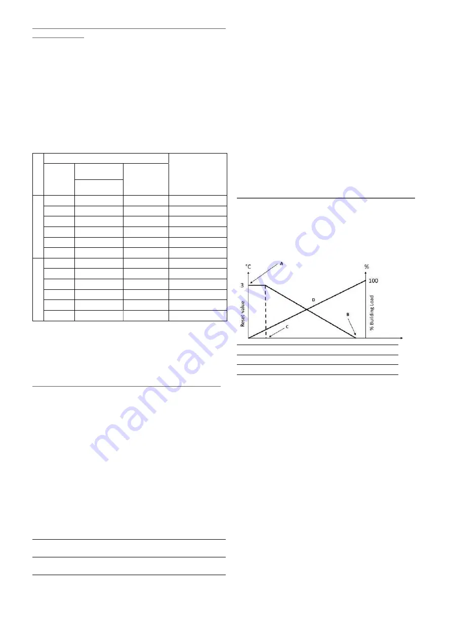
Reset is a linear function based on three parameters:   

•  A reference at which reset is zero (outdoor temperature 

or delta T or 4-20 mA signal – no reset value).

•  A reference at which reset is maximum  

(OAT or delta T or 4-20 mA signal – full reset value).

•  The maximum reset value.

Reset example in Cooling mode

10

Outdoor air temperature (OAT)

20

3

Heat exchanger delta T

5

4

Analogue input

20

no reset

selection

full reset

Legend:

A: Maximum reset value

B: OAT / delta T / 4-20 mA for no reset

C: OAT / delta T / 4-20 mA for full reset

D: Building load

8.6 -  Capacity control

The Touch Pilot Junior control adjusts the number of active 
compressors to keep the heat exchanger temperature at its 
setpoint. The precision with which this is achieved depends 

on.the.capacity.of.the.water.loop,.the.flow.rate,.the.load,.and.

the number of stages available on the unit. 

To determine the optimum moment at which to add or 
withdraw a capacity stage, the control system continuously 
takes account of the temperature error with respect to the 
control point, as well as the rate of change in this error and the 
difference between entering and leaving water temperatures. 

If the unit undergoes too many starts within an hour or the 
compressor runs below one minute each time it is started, this 
automatically brings about reduction of compressor starts, which 
makes the controlled leaving water temperature less precise. 

The high pressure, low pressure or water loop conditions can 
also affect temperature control accuracy. Compressors are 
started and stopped in a sequence designed to equalise the 
number of start-ups (value weighted by their operating time).

Summary of Contents for AquaSnap 30WG Series

Page 1: ...CONTROLS MANUAL Operation instructions Original document Touch Pilot Junior Control 30WG 30WGA 61WG...

Page 2: ...ns 10 5 SETTING UP TOUCH PILOT JUNIOR CONTROL 11 5 1 Reading the Welcome screen 11 5 2 Exploring the Synoptic screen 11 5 3 Starting Stopping the unit 11 5 4 Setting the schedule 12 5 5 Display settin...

Page 3: ...t any time without notice 8 10 Additional space heating control 28 8 11 Built in DHW and space heating control HDC 29 8 12 Condensing pressure control optional 30 8 13 Master Slave control 30 9 DIAGNO...

Page 4: ...instructions prior to proceeding with any work Pay attention to all safety warnings The information provided herein is solely for the purpose of allowing customers to operate and service the equipment...

Page 5: ...trical cables and conduits terminal box covers and motor frames with great care 2 CONTROLLER OVERVIEW 2 1 Control system 30WG 30WGA 61WGunitscomewiththeTouchPilotJunior control that serves as a user i...

Page 6: ...f the green LED is not flashing this indicates a LEN bus wiring problem 3 4 Pressure transducers The control implements three types of pressure transducers where two pressure transducers high pressure...

Page 7: ...ustomer safety loops Condenser 3 way valve SIOB cir A 80 80 Used to control the water flow on the condenser side Boiler SIOB cir A 69 70 Used to command a boiler Running SIOB cir A 37 38 Used to signa...

Page 8: ...me screen will be displayed 4 2 Connections Connections are located on the bottom side of the controller The controller comes with two RS485 ports where the first port is used to connect to CCN Carrie...

Page 9: ...er password User password required Legend Genunit Config Schedule HDC Configuration Date Time Pump Configuration Holiday Reset Config Control Identification Heat Cool Config Broadcast User Configurati...

Page 10: ...rt no action taken on the unit Steady icon Alarm s active on the unit see section 9 5 OTHER SCREENS Login screen Parameters screen s Login Confirm advanced access login Save changes Logout Reset the u...

Page 11: ...d 5 SETTING UP TOUCH PILOT JUNIOR CONTROL 5 1 Reading the Welcome screen The Welcome screen is the first screen shown after starting the user interface It displays the application name as well as the...

Page 12: ...is set the selected period will be presented in the form of the green band on the timeline 7 Press the Save button to save your changes or the Cancel button to exit the screen without making modificat...

Page 13: ...r level security ensures that only authorised users are allowed to modify critical unit parameters Only logged in users are allowed to access the Configuration menu It is strongly recommended to chang...

Page 14: ...ion is from a PC using a web browser with Java IMPORTANT UsefirewallsandVPNforsecureconnection 6 2 Opening the web interface To access theTouch Pilot Junior control enter the IP address of the unit in...

Page 15: ...ditional features some tables may contain parameters that cannot be configured for a given unit General Parameters Menu GENUNIT No Point name Status Unit Displayed text Description 1 CTRL_TYP 0 to 2 L...

Page 16: ...emperature circuit A 4 SST_B C Saturated Suction Tp B Saturated suction temperature circuit B 5 SUCT_A C Gas Suction Temp A Compressor suction temperature circuit A 6 SUCT_B C Gas Suction Temp B Compr...

Page 17: ...pen close Remote Setpoint Switch2 Remote Setpoint Switch 2 6 LIM_SW1 open close Limit Switch 1 Status Demand limit switch 1 7 LIM_SW2 open close Limit Switch 2 Status Not applicable please ignore this...

Page 18: ...oint Evaporator water delta temp setpoint 12 CL_WdpSp kPa Cool Water DP Setpoint Evaporator water delta pressure setpoint 13 CL_DvPos 0 to 100 Cool Pump drive position Evaporator pump drive position 1...

Page 19: ...ber of starts compressor A1 7 hr_cp_a2 hour Compressor A2 Hours Operating hours compressor A2 8 st_cp_a2 Compressor A2 Starts Number of starts compressor A2 9 hr_cp_a3 hour Compressor A3 Hours Operati...

Page 20: ...Displayed text Description 1 m_delay no yes Delay Active Start up delay in effect 2 m_2ndspt no yes Second Setpoint Active Second setpoint in use The setpoint used during unoccupied periods 3 m_reset...

Page 21: ...a given unit Genunit Config Menu GENCONF No Point name Status Default Unit Displayed text Description 1 lead_cir 0 to 2 0 Cir Priority Sequence Circuit priority 2 0 Auto 1 A Lead 2 B Lead 0 Automatic...

Page 22: ...the selected language English by default Heat Cool Config Menu HCCONFIG No Point name Status Default Unit Displayed text Description 1 cr_sel 0 to 3 0 Cooling Reset Select Cooling reset selection 2 hr...

Page 23: ...fu 30 1 to 52 2 40 5 C OAT Full Reset Value OAT max reset value 12 dt_hr_no 0 to 14 1 0 C Delta T No Reset Value Delta T no reset value 13 dt_hr_fu 0 to 14 1 0 C Delta T Full Reset Value Delta T max r...

Page 24: ...onth Day of the month 2 month 1 to 12 Month of year Month 3 year 20nn Year Year 4 dow Monday Sunday Day of Week Day of the week Time HH MM 5 hour 0 to 24 hour Hour Hour 6 minute 0 to 59 min Minute Min...

Page 25: ...operate in Cooling mode only The unit operation is based on the following parameters Unit On Off status This parameter indicates whether the unit is shut down not authorised to start or in operation...

Page 26: ...mpdel for cooler OR 4 Set PumpAuto Rotation Delay cdpmpdel for condenser Pump Auto Rotation Delay clpmpdel cdpmpdel 24 to 3000 h 48 h 8 4 3 Pump speed control If the pump with variable flow option has...

Page 27: ...g setpoint reset which can be applied if the condensing setpoint control depends on outdoor air temperature reading reset source OAT Cooling mode 30WG 30WGA 61WG Cooling control point reset is used to...

Page 28: ...et boiler manual command 1 Navigate to the Configuration menu 2 Select Heat Cool Config HCCONFIG 3 Set Boiler Manual Command boil_on Boiler Manual Command boil_on No OAT sensor logic is applied Yes Bo...

Page 29: ...ntinue to operate as described earlier The electric heater stages operate only in the heating mode but not during domestic hot water production 8 11 4 Heating or domestic hot water mode A three way va...

Page 30: ...ch Pilot Junior continuously optimises system operation to obtain the best system efficiency by controlling the number of fans required for any thermal load and outside temperature conditions 8 12 3 C...

Page 31: ...2 Select Current Alarms 3 The list of active alarms will be displayed 9 3 Resetting alarms The alarm can be reset either automatically by the control or manually through the touch panel display or th...

Page 32: ...12002 Circuit B Discharge Pressure Transducer Failure As above Circuit B shuts down As above 12004 Circuit A Suction Pressure Transducer Failure As above Circuit A shuts down Automatic up to 3 alarms...

Page 33: ...stand alone mode Automatic if communication is restored 10031 Unit is in CCN emergency stop Network emergency stop command Unit shuts down Automatic if emergency stop is deactivated 10032 Cooler pump...

Page 34: ...enser water loop failure pump overload Water loop pressure drop too low Unit shuts down Automatic 11107 Condenser water loop failure switch fail Switch fault Unit shuts down Automatic 6 times within 2...

Page 35: ...nd no serious damage can occur to your equipment The Manufacturer provides a wide range of service contracts which embrace the assistance of highly qualified HVAC engineering professionals ready to he...

Page 36: ...rder No 10161 09 2016 Supersedes order No New Manufacturer Carrier SCS Montluel France Manufacturer reserves the right to change any product specifications without notice Printed in the European Union...

Reviews: