


94
7. Allow excess water to drain prior to replacing segments in
the wheel. A small amount of water remaining in the
wheel will be dried out by the airflow.
FILTERS
Clean or replace at start of each heating and cooling seasons, or
more often if operating conditions require (based on filter man-
ufacture recommendation or filter status alarm indication).
OUTDOOR-AIR INLET SCREENS
Clean screens with steam or hot water and a mild detergent at
the beginning of each heating and cooling season. Do not use
throwaway filters in place of screens.
EnergyX Component Lubrication
All component bearings are sealed and do not require lubrication.
EnergyX Wheel Drive Adjustment
The wheel motor and drives do not require adjustment. The
wheel drive pulley is secured to the drive motor shaft by a set
screw. The set screw is secured with removable locktite to pre-
vent loosening. Annually confirm set screw is secure. The
wheel drive belt is a urethane stretch belt designed to provide
constant tension throughout the life of the belt. Inspect the
drive belt annually for proper tracking and tension. A properly
tensioned belt will turn the wheel immediately after power is
applied with no visible slippage during start-up.
EnergyX Wheel Air Seal Adjustment
Diameter seals are provided on each wheel cassette to mini-
mize transfer of air between the counter flowing airstreams.
Follow below instructions if adjustment is needed.
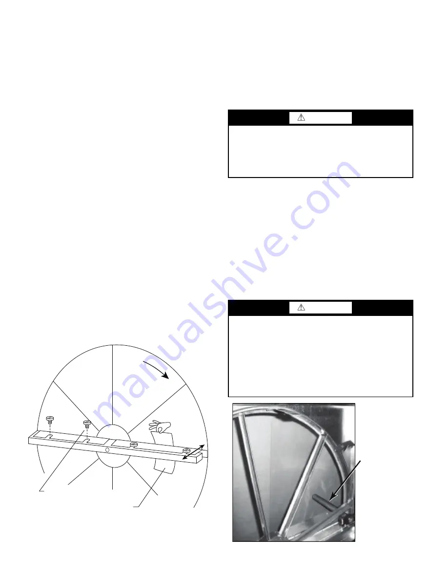
1. Loosen diameter seal adjusting screws and back seals
away from the wheel surface. See Fig. 46.
2. Rotate the wheel clockwise until two opposing spokes are
hidden behind the bearing support beam.
3. Using a folded piece of paper as a feeder gauge, position
the paper between the seal and wheel surface.
4. Adjust the seal towards wheel surface until a slight friction
on the feeder gauge (paper) is detected while moving the
gauge along the length of the spoke.
5. Re-tighten adjustment screws and re-check clearance with
the feeder gauge.
Fig. 46 — Diameter Seal Adjustment
Wheel and Segment Removal / Installation
The wheel and segments represent a substantial portion of the
value of the cassette therefore must be handled with care and
never be dropped. Use a suitable crate or harness to lift wheel
and segments to a roof surface, never use the shipping cartons
for this purpose. Wheel and segments may require “slight” per-
suasion during installation and removal but never forced or im-
pacted with a hammer or similar tool. The wheel assembly can
be removed and installed or the wheel or segments can be re-
moved from the assembly.
The ERV wheel on 3 ton units is a 19 inch whole wheel assem-
bly. ERV wheels on 4 to 25 ton units are segmented wheel as-
semblies. Follow the correct section below for removing and
installing specific wheels from their assemblies. To remove or
install the whole assembly, simply side in or out the assembly
noting the motor power plug.
Wheel Segment Removal / Installation
1. Turn off, lockout and tag-out electrical power to unit.
2. Open access door to the EnergyX
module on back side of
the unit.
3. Slide the entire wheel assembly out until the necessary
segment(s) of the wheel can be accessed. Support the
weight of the wheel assembly as necessary to avoid dam-
age to wheel or unit.
Fig. 47 — Wheel Stop
Rotation
Adjusting Screws
Feeler Gauge
To
Adjust
WARNING
UNIT DAMAGE HAZARD
Failure to follow this caution may result in equipment dam-
age.
The weight of the wheel assembly must be supported when
the assembly is extended from the unit chassis to avoid
damage to wheel or unit.
WARNING
PERSONAL INJURY HAZARD
Failure to follow this caution may result in personal injury.
Weight of the installed segment will cause the wheel to ac-
celerate in rotation as segments are removed. Failure to
maintain control of the wheel rotation while installing all
segments could cause severe injury to fingers or hand
caught between revolving spokes and the bearing support
beam. The handle of a tool such as a hammer, should be in-
serted through spokes and above or below bearing support
beams to limit rotation of unbalanced wheel. See Fig. 47.
Hammer used
as a “stop”
Summary of Contents for /50HC 04-28
Page 69: ...69 Fig 24 Typical Control Diagram for 48HC 04 14 Units 48HC 08 09 shown ...
Page 70: ...70 Fig 25 Typical Power Diagram for 48HC 04 14 Units 48HC 08 09 shown ...
Page 71: ...71 Fig 26 Typical Control Diagram for 50HC 04 14 Units 50HC 14 shown ...
Page 72: ...72 Fig 27 Typical Power Diagram for 50HC 04 14 Units 50HC 14 Non Humidi MiZer shown ...
Page 73: ...73 Fig 28 Typical Control Diagram 48HC 17 28 Units ...
Page 74: ...74 Fig 29 Typical Control Diagram 50HC 17 28 Units ...
Page 75: ...75 Fig 30 Typical Humid MiZer Power Diagram and Component Arrangement 48 50HC 17 28 Units ...
Page 76: ...76 Fig 31 Typical Non Humid MiZer Power Diagram and Component Arrangement 48 50HC 17 28 Units ...
Page 89: ...89 Fig 42 Modulating ERV Wiring Schematic ...
Page 90: ...90 Fig 43 EnergyX ERV Control Box Component Layouts ...
Page 101: ...101 Fig 59 Exhaust Fan Assembly Removal Exhaust Fan Assembly ...
Page 141: ......