13
ENG
Heos
+0300078EN - rel. 1.6 - 23.11.2017
2.8 Functional
diagrams
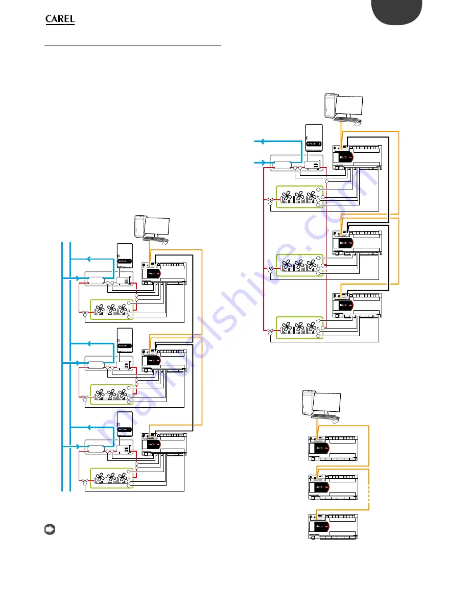
There are two possible showcase/cold/room confi gurations. The fi rst
involves the various units being fi tted individually with their own
compressor and condenser, meaning the showcase is completely
independent, and shares the cooling water loop with the rest of the
system. In the second case, the condenser is shared and consequently the
Slave showcases are only fi tted with the evaporator and corresponding
electronic expansion valve, while the compressor is controlled by the
Master board.
The system confi gurations can be set from a terminal (pGDe) as illustrated
in the chapter on Commissioning; while on the showcase itself a PLD is
normally used to display the temperature and any alarm signals.
Defrosts can be coordinated via the pLAN that controls a maximum of 6
units, or alternatively by the supervisor
1.
Stand-alone confi guration
In this case, each showcase/cold room has its own compressor, controlled
by the corresponding board, which manages all system devices
(expansion valve, showcase temperature control, alarms….).
The Master/Slave network is used for to coordinate defrosts, lights and
curtain switch; otherwise these functions must be managed by the
supervisor.
P
T
P
T
T
Waterloop
Conden. Unit
BMS
Cabinet
Master
Slave1
pLAN Net
w
o
rk
RS485 Super
visor
y S
yst
ems
Slave2
Cabinet
T
T
T
T
T
P
T
P
T
Conden. Unit
Cabinet
T
T
T
P
T
P
T
Conden. Unit
Fig. 2.n
Note:
For the electrical connections, see the general connection
diagram in par. 2.9. If a master/slave network or multi-evaporator pLAN is
confi gured, the controller addresses should be set following the
procedure shown in chapter 9.1 or using the Wizard (chap. 5
“Commissioning”)
2.
Multi-evaporator Master/ Slave network
The Master controller manages the compressor and coordinates the
functions of the 5 Slave controllers connected via the pLAN. Each Slave
controller manages the individual showcase and has a PLD user terminal
for temperature monitoring. Each controller, both Master and Slave,
is connected to the supervisor network. The Master only shares the
evaporation pressure, and not the corresponding temperature.
P
T
P
T
T
T
T
Waterloop
Conden. Unit
BMS
Cabinet
Master
Slave1
pLAN Net
w
o
rk
RS485 Super
visor
y S
yst
ems
Slave2
Cabinet
Cabinet
T
T
T
T
T
T
T
T
T
Fig. 2.o
3.
RS485 supervisor network
A maximum of 199 number Heos controllers (Master or Slave) can be
connected to the supervisor network (via CAREL or Modbus® protocol).
RS485 Super
visor
y S
yst
ems
1
2...
...199
BMS
Fig. 2.p
Supervisor network layout with various Heos controllers connected,
1-199
Summary of Contents for Heos
Page 2: ......
Page 4: ...4 ENG Heos 0300078EN rel 1 6 23 11 2017 ...
Page 6: ......
Page 57: ...57 ENG Heos 0300078EN rel 1 6 23 11 2017 Notes ...
Page 58: ...58 ENG Heos 0300078EN rel 1 6 23 11 2017 Notes ...
Page 59: ......


