30
ENG
"humiFog direct" +0300073EN rel. 1.4 - 29.03.2022
10. CONNECTIVITY
10.1 Webserver
The web server is a very interesting function when the user has a local
network available that humiFog Direct can be connected to. The physical
local network connection uses the Ethernet port with RJ45 connector
on the humidifi er controller (see par. Serial or Ethernet communication)
and a normal Ethernet cable (category 5). The integrated web server on
the humiFog Direct c.pHC controller is used to confi gure and monitor
the main unit parameters directly from a PC, tablet or smartphone. By
opening an internet browser, the humidifi er can be accessed from the
local network via the humiFog Direct unit’s IP address.
10.1.1 IP address and network confi guration
An IP address is a numerical code that identifi es the modem, computer,
smartphone or any other device connected to a network, so as that these
can communicate with one another. Typically the IP address of multiple
devices connected to the same network is identical, except for a few
numbers.
EXAMPLE:
•
192.168.1.1 device #1 connected to the network
•
192.168.1.2 device #2 connected to the same network
•
192.168.2.25 device #3 connected to the same network
Remember that when wanting to connect several devices to the
same network, a switch is required (this can be supplied by Carel, P/N
KITSE08000).
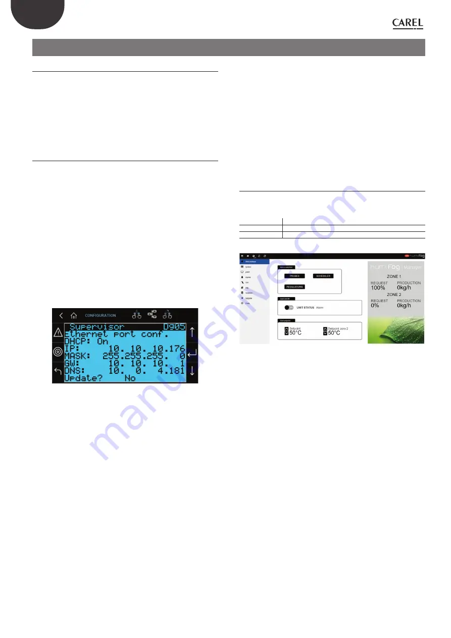
The IP address of the humiFog Direct unit is shown on the display, under:
•
D. Settings
•
d. Unit networks
•
g. Supervisor
Dg05. Ethernet supervision port confi guration: DHCP and IP address
Fig. 10.a
To access the web server, to open an internet browser and enter the
IP address, followed by /commissioning/index.html (in this case type
10.10.10.176/commissioning/index.html in the browser’s address bar).
IP addresses may be :
•
dynamic (if using the DHCP function that automatically assigns an IP
address when a device is connected)
•
static (if there is no DHCP function or it cannot be used, with manual
assignment of the IP address directly by the user).
If using a dynamic IP address via the DHCP function on the server,
DHCP needs to be enabled on screen Dg05 on the humiFog Direct
unit. The IP address shown on the screen will be assigned automatically.
The advantage of this feature is that the server and humiFog Direct
communicate directly, and there is no need to confi gure the network
parameters (subnet mask and gateway). The disadvantage is that if
adding other devices to the same network with humiFog Direct off and
not connected, the IP address originally assigned to the unit may change,
and therefore the new address needs to be set on screen Dg04 and
copied into the browser’s address bar.
With a static IP address (with DHCP OFF as by default), on screen Dg05
enter the network parameters manually, as provided by the local network
installer. Usually subnet mask and gateway have predefi ned values (which
must be known), while the IP address can be assigned sequentially in
relation to another device connected to the same network.
The default network confi gurations for the c.pHC are:
•
unit IP address: 192.168.0.1
•
subnet mask: 255.255.255.0
•
gateway: 192.168.0.1
Important:
in the “capacity extension” function (described in paragraph
6.2.2), DHCP cannot be activated, otherwise the units would not be able
to communicate together. DHCP must be disabled on screen Dg05 (as
by default).
Important:
the controller is not accessible directly via the internet as a
fi rewall guarantees remote access only over a secure connection (Carel
tERA cloud connection). Consequently, outside of the local network the
controller cannot be accessed, even if the network administrator assigns
a public address.
10.1.2 Webserver
functions
Once having accessed the webserver, to log in and access the various
menu items, use the credentials listed in Table 8.a, according to the type
of user.
ID
PW
Service
77
User
44
Tab. 10.a
Fig. 10.b
Web interface
Once having logged in, the webserver "HOME" page is displayed, also called the
web interface. This page displays the main information on the unit, including:
•
unit status
•
zone request and production
•
set point: the value can be set for each zone via webserver
•
probes: information on the probe readings and confi guration of the main and
limit probe Select the type of signal and defi ne the minimum and maximum
values
•
scheduler: enable and set the daily and weekly time bands.
•
control: select the type of control, set point, diff erential and minimum/maximum
settings
System
The system page shows the main information on the application, the available
memory, network and system settings. There is also information for registering the
unit on the tERA remote cloud service.
pGD1
The pGD1 page opens a keyboard for advanced confi guration of the unit.
Alarms
Display active alarms and alarm log.
Unit
Display the values of the digital and analogue inputs and outputs on the unit.
Summary of Contents for DLAQ2DF100
Page 1: ...NO POWER SIGNAL CABLES TOGETHER READ CAREFULLY IN THE TEXT humiFog direct User manual...
Page 2: ......
Page 4: ...4 ENG humiFog direct 0300073EN rel 1 4 29 03 2022...
Page 42: ...42 ENG humiFog direct 0300073EN rel 1 4 29 03 2022 14 2 Two zone wiring diagram GA1 Fig 14 b...
Page 46: ......
Page 47: ......


