24
Esempio di funzionamento:
Cabinet On/Off
Cabinet MODULANTE
set-point = 50%
set-point = 50%
On = <45%
max. On = <45%
Off = >50%
Off = >50%
Modulazione tra 45 e 50% U.R.*
* Il cabinet per condotta prevede la stessa logica di fun-
zionamento per entrambi i regolatori.
Nel caso si necessiti di differenziali diversi, sconsigliamo
comunque valori più piccoli, fare riferimento al capitolo
11.8 ai parametri P01 (versione On/Off) e P07 (versione
PROPORZIONALE).
Indicazioni e Allarmi
Il regolatore CR72 è in grado di visualizzare a display una
serie di allarmi:
HIA
lampeggia quando l’umidità sale al di sopra del
set fissato di alta umidità (set-point + P15).
LOA
lampeggia quando l’umidità scende al di sotto del
set fissato di bassa umidità (set-point - P14).
SEA
lampeggia quando il segnale sonda assume
valori fuori range.
ALA
lampeggia quando il funzionamento del sistema
viene interrotto dall’On-Off remoto.
EEE
lampeggia quando viene rilevato un errore nel
circuito del CR72.
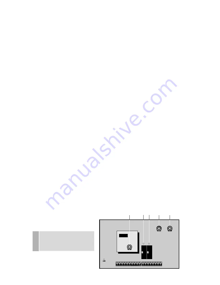
Impostazione scheda AD4
Sulla scheda AD4, inserita nel cabinet sono presenti tre
LEDs per segnalazioni: DL1- scheda in tensione, DL2 -
linea aria attiva, DL3 - linea acqua attiva. Vi sono inoltre
tre trimmer, T1 - T2 - T3, per la gestione del ciclo di puli-
zia suddivisa in tre fasi:
T1 - Tempo di ON
Fissa il tempo massimo di funzionamento dell’impianto qua-
lora la richiesta di umidificazione sia continua; è regolabile
da 1 a 60 min.;
T3 - Ciclo di asciugatura
Regola il tempo di attivazione della sola aria (acqua Off)
durante il ciclo di pulizia, al fine di asciugare completa-
mente le teste; è impostabile da 20 a 90 sec.
NOTA: questa fase viene ripetuta ogni qualvolta l’impianto
si ferma per il raggiungimento dell’umidità richiesta.
T2 - Tempo di OFF
Definisce il tempo di fermata completa dell’impianto.
Durante questo periodo la pessione dell’aria dell’impianto
si annula completamente; lo spillo della testa chiude e
pulisce l’orifizio di uscita dell’acqua atomizzata. Il tempo di
Off è regolabile da 1 a 60 sec.
ATTENZIONE: evitare di toccare la scheda con le mani e
scaricare il cacciavite prima di intervenire sui trimmer.
Example:
ON/OFF cabinet
MODULATING cabinet
set-point = 50%
set-point = 50%
ON = <45%
max. ON = <45%
OFF = >50%
OFF = >50%
Modulation between 45 and 50% rH*
* The two regulators used in duct applications have the
same functioning logic.
If your application requires 2 different differentials, please
see parameters P01 (ON/OFF version) and P07 (PRO-
PORTIONAL version) below. However, we suggest that
you should not decrease too much the values indicated
above.
Indications and Alarms
In case of OFF-normal conditions, the CR72 will display
the following messages:
HIA
blinks when the humidity value is higher than the
high humidity set-point (set-point + P15).
LOA
blinks when the humidity value is lower than the
low humidity set-point (set-point - P14).
SEA
blinks when the probe measures out-of-range
values.
ALA
blinks when the remote ON/OFF circuit is open.
EEE
blinks if an error in the CR72 circuit is detected.
Adjusting the AD4 card
On the AD4 board inside the cabinet are present three
LED’s for signal: DL1 - board in tension, DL2 - air line
actived, DL3 - water line actived. And also, three potentio-
meters, T1, T2, T3, for the management of the cleaning
cycle, in three different parametres:
T1 - Functioning time
Maximum ON time on a call for humidity (1 to 60minutes).
T3 - Drying up cycle
During the cleaning cycle it will be possible to use com-
pressed air only (water line OFF) so as to dry up the
nozzles. The drying up function can be adjusted from 20
to 90seconds.
NOTE: once set up, the drying cycle will be repeated any
time the system stops after having reached the set humi-
dity conditions.
T2 - OFF routine
It is the time-interval during which the system remains
OFF. During this time the pin of the atomizing nozzle
cleans the small opening of the nozzle and removes any
calcareous deposit. Adjustable from 1 to 60seconds.
WARNING: do not touch the board. Before adjusting the
potentiometers, remove the static charge from the screw-
driver.
.......
.......
T1
T2
T3
DL2 DL3
DL1
DL1 LED verde acceso - scheda in tensione
Green LED ON - board in tension
DL2 LED rosso acceso - linea aria attiva
Red LED ON - air line activated
DL3 LED rosso acceso - linea acqua attiva
Red LED ON - water line activated
fig. 18


