


10
NOTE
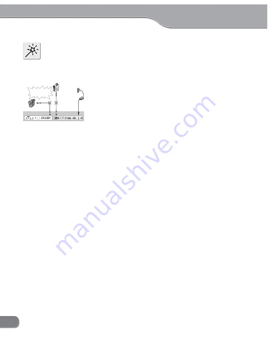
Do not connect DV cameras to
both of the front and rear DV ter-
minals at the same time (HUB
connection not allowed.).
DV camera
4pin
Wall socket
AC adaptor
6pin
Do not connect the DV
devices to both the front
and rear DV terminals at
the same time.
Front
Rear
6pin
4pin
DV camera
TwinPact 100
3. RGB IN mode : Scan Converter mode (Screen Capture mode)
This mode is used for displaying a computer screen on a TV moni-
tor by converting signal coming from the computer into signal for
TV monitors. In this mode, the TwinPact 100 converts signals rep-
resenting the computer screen coming from the RGB input con-
nector ((6) on P.7) on the back of the unit into video signal for
displaying that screen on a TV monitor, and outputs it via the video
output connector ((2) and (3) on P.7). In addition, if sound is output
from the computer's sound card to the audio input connector ((5)
on P.7), the sound is output through the audio output connector ((4)
on P.7). These RGB or audio output signals can be output to TV
monitor or SVHS VCR.
In this mode, the TwinPact 100 converts both of RGB and audio
outputs into DV signal at the same time and outputs it via the 4-pin
DV connector on the front of the unit or the 6-pin DV connector on
the back.
You can capture DV output as a video into a DV device such as DV
camera or as a motion picture into a hard disk by connecting the
computer's IEEE1394 connector and using the accessory software.
Screen action shown on a computer monitor and sound output
from the computer can be captured as DV data and saved into the
computer's hard disk.
Summary of Contents for TwinPact 100
Page 1: ...User Manual...
Page 10: ......
Page 11: ......
Page 33: ...23 Click OK 11 11 Playback the captured video and check the content 12 12...


