


No.
Parts Name
Main Unit
Remarks
Reference
Adjastment during
parts replacement
[8] NFC PCB
Control Panel Unit
MF727Cdw /
726Cdw : UN20
“Removing the NFC PCB
(MF727Cdw / 726Cdw)” on page
171
-
[9] Fixing/Fixing Power Sup-
ply Cooling Fan
Product Configura-
tion
FM1
“Removing the Fixing/Fixing Power
Supply Cooling Fan Unit” on page
180
-
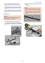
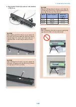
[10] Duplex Feeding Fan
Rear Cover Rib Unit FM2
“Removing the Duplex Feeding
Fan” on page 181
-
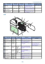
■ 2/2
[12]
[13]
[14]
[11]
[15]
[16]
[17]
[18]
[19]
No.
Parts Name
Main Unit
Remarks
Reference
Adjastment during parts re-
placement
[11] Relay PCB
Product Con-
figuration
UN5
“Removing the Relay PCB” on page
168
-
[12] Duplex Reverse Drive
Unit
Product Con-
figuration
“Removing the Duplex Reverse
Drive Unit” on page 179
-
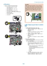
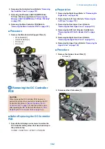
[13] DC Controller PCB
Product Con-
figuration
UN1
“Removing the DC Controller PCB”
on page 162
“Before Replacing the DC Con-
troller PCB” on page 162
“After Replacing the DC Control-
ler PCB” on page 163
[14] Off Hook PCB
Product Con-
figuration
MF728Cdw /
727Cdw /
726Cdw /
725Cdn : UN17
“Removing the Off Hook PCB
(MF728Cdw / 727Cdw / 725Cdn)” on
page 172
-
[15] Speaker
Product Con-
figuration
MF728Cdw /
727Cdw /
726Cdw /
725Cdn : SP1
“Removing the Speaker
(MF728Cdw / 727Cdw / 725Cdn)” on
page 183
-
[16] Driver PCB
Product Con-
figuration
UN2
“Removing the Driver PCB” on page
167
-
[17] Main Drive Unit
Product Con-
figuration
“Removing the Main Drive Unit” on
page 172
-
[18] Low Voltage Power
Supply Unit
Product Con-
figuration
“Removing the Low Voltage Unit” on
page 165
-
4. Disassembly/Assembly
155
Summary of Contents for MF720 Series
Page 1: ...Revision 2 0 MF720 Series Service Manual...
Page 12: ...Product Overview 1 Product Lineups 5 Product Features 7 Specifications 8 Name of Parts 14...
Page 79: ...4 Click Import Export Import 1 2 2 Technical Explanation 71...
Page 103: ...Durable Parts No durable parts is set for this product 3 Periodical Service 95...
Page 104: ...Periodical Services No periodical service is set for this product 3 Periodical Service 96...
Page 232: ...Adjustment 5 Overview 225 Adjustment at Parts Replacement 226...
Page 248: ...Troubleshooting 6 Test Print 241 Trouble shooting items 243 Version Upgrade 244 Debug Log 248...
Page 258: ...Error Jam Alarm 7 Outline 251 Error Codes 252 Jam Code 257...
Page 267: ...Service Mode 8 Overview 260 COPIER 264 FEEDER 300 FAX 302 TESTMODE 308...
Page 322: ...APPENDICES Service Tools 315 General Circuit Diagram 316 Print Sequence 317 Backup Data 318...