

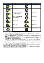


Symbols
Explanation
Symbols
Explanation
1x
Disconnect the connector.
Connect the power cable.
1x
Connect the connector.
Disconnect the power cable.
1x
Remove the cable/wire from the
cable guide or wire saddle.
Turn on the power.
1x
Install the cable/wire to the cable
guide or wire saddle.
Turn off the power.
1x
Remove the screw.
1x
Loosen the screw.
1x
Install the screw.
1x
Tighten the screw.
Cleaning is needed.
Measurement is needed.
The following rules apply throughout this Service Manual:
1. Each chapter contains sections explaining the purpose of specific functions and the relationship between electrical and
mechanical systems with reference to the timing of operation.
In the diagrams,
represents the path of mechanical drive; where a signal name accompanies the symbol, the arrow
indicates the direction of the electric signal.
The expression "turn on the power" means flipping on the power switch, closing the front door, and closing the delivery unit
door, which results in supplying the machine with power.
2. In the digital circuits, '1' is used to indicate that the voltage level of a given signal is "High", while '0' is used to indicate "Low".
(The voltage value, however, differs from circuit to circuit.) In addition, the asterisk (*) as in "DRMD*" indicates that the DRMD
signal goes on when '0'.
In practically all cases, the internal mechanisms of a microprocessor cannot be checked in the field. Therefore, the operations
of the microprocessors used in the machines are not discussed: they are explained in terms of from sensors to the input of
the DC controller PCB and from the output of the DC controller PCB to the loads.
The descriptions in this Service Manual are subject to change without notice for product improvement or other purposes, and
major changes will be communicated in the form of Service Information bulletins.
All service persons are expected to have a good understanding of the contents of this Service Manual and all relevant Service
Information bulletins and be able to identify and isolate faults in the machine.
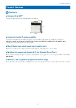
Introduction
Summary of Contents for MF720 Series
Page 1: ...Revision 2 0 MF720 Series Service Manual...
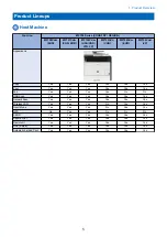
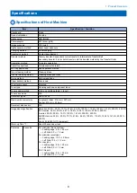
Page 12: ...Product Overview 1 Product Lineups 5 Product Features 7 Specifications 8 Name of Parts 14...
Page 79: ...4 Click Import Export Import 1 2 2 Technical Explanation 71...
Page 103: ...Durable Parts No durable parts is set for this product 3 Periodical Service 95...
Page 104: ...Periodical Services No periodical service is set for this product 3 Periodical Service 96...
Page 232: ...Adjustment 5 Overview 225 Adjustment at Parts Replacement 226...
Page 248: ...Troubleshooting 6 Test Print 241 Trouble shooting items 243 Version Upgrade 244 Debug Log 248...
Page 258: ...Error Jam Alarm 7 Outline 251 Error Codes 252 Jam Code 257...
Page 267: ...Service Mode 8 Overview 260 COPIER 264 FEEDER 300 FAX 302 TESTMODE 308...
Page 322: ...APPENDICES Service Tools 315 General Circuit Diagram 316 Print Sequence 317 Backup Data 318...