


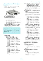


8. PASCAL adjustment
Enter the values shown on the label that comes with the
part in the following service mode items.
Enter the values of OFST-P-Y, OFST-P-M, OFST-P-C,
and OFST-P-K in the following service mode, and write
the entered values on the service label.
• COPIER>ADJUST>PASCAL>OFST-P-Y (Y
density adj at test print reading)
• COPIER>ADJUST>PASCAL>OFST-P-M (M
density adj at test print reading)
• COPIER>ADJUST>PASCAL>OFST-P-C (C
density adj at test print reading)
• COPIER>ADJUST>PASCAL>OFST-P-B (Bk
density adj at test print reading)
9. Copyboard geometric adjustment
Enter the values shown on the label that comes with the
part in the following service mode items.
• COPIER > ADJUST > ADJ-XY > ADJ-X (Adj of img
pstn in book mode: vert scan)
• COPIER > ADJUST > ADJ-XY > ADJ-Y (Adj of img
pstn in book mode: (horizontal scanning direction)
• COPIER > ADJUST > ADJ-XY > ADJ-X-MG (Fine
adj image ratio: vertical scanning)
Enter the values in the foregoing service mode.
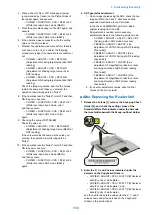
10. ADF geometric adjustment
1. On an image copied using the ADF, check the non-
image width in the X and Y directions and the
expansion/contraction in the X direction.
In the case of E353MGMH, perform 2-sided
original reading from the ADF.
If adjustment is needed, enter necessary
adjustment values in the following service mode:
• COPIER > ADJUST > ADJ-XY > ADJ-Y-DF
(Adj img pstn in ADF mode:horz scan)
• FEEDER > ADJUST > DOCST (Fine
adjustment of VSYNC timing at ADF reading
[front side])
• FEEDER > ADJUST > DOCST2 (Fine
adjustment of VSYNC timing at ADF reading
[back side])
• FEEDER > ADJUST > LA-SPD (Fine
adjustment of magnification ratio in vertical
scanning direction at ADF stream reading
[front side])
• FEEDER > ADJUST > LA-SPD2 (Fine
adjustment of magnification ratio in vertical
scanning direction at ADF stream reading
[back side])
2. If you enter adjustment values, write the final
values on the service label.
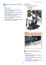
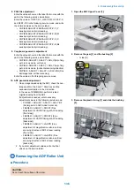
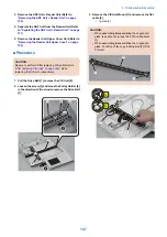
Removing the ADF Roller Unit
■ Procedure
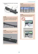
CAUTION:
Do not touch the surface of the roller.
1. Open the ADF Upper Cover [1].
[1]
2. Remove the gear [1] and the bushing [2].
• 1 claw [3]
[1]
[2]
[3]
1x
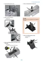
3. Remove the plastic E-ring [1] and slide the bushing
[2].
[1]
[2]
4. Disassembly/Assembly
136
Summary of Contents for MF720 Series
Page 1: ...Revision 2 0 MF720 Series Service Manual...
Page 12: ...Product Overview 1 Product Lineups 5 Product Features 7 Specifications 8 Name of Parts 14...
Page 79: ...4 Click Import Export Import 1 2 2 Technical Explanation 71...
Page 103: ...Durable Parts No durable parts is set for this product 3 Periodical Service 95...
Page 104: ...Periodical Services No periodical service is set for this product 3 Periodical Service 96...
Page 232: ...Adjustment 5 Overview 225 Adjustment at Parts Replacement 226...
Page 248: ...Troubleshooting 6 Test Print 241 Trouble shooting items 243 Version Upgrade 244 Debug Log 248...
Page 258: ...Error Jam Alarm 7 Outline 251 Error Codes 252 Jam Code 257...
Page 267: ...Service Mode 8 Overview 260 COPIER 264 FEEDER 300 FAX 302 TESTMODE 308...
Page 322: ...APPENDICES Service Tools 315 General Circuit Diagram 316 Print Sequence 317 Backup Data 318...